Home › Engine / Hybrid System › 8NR-FTS (ENGINE MECHANICAL) › ENGINE UNIT › 2019.09–2020.08
NM32H0E _51 Engine / Hybrid System _060377 8NR-FTS ENGINE MECHANICAL _0296145 ENGINE UNIT DE DETAILS F

8NR-FTS ENGINE MECHANICAL  ENGINE UNIT  DETAILS  VALVE MECHANISM  


CONSTRUCTION


a.

A high-expansion cycle (Atkinson cycle) is used to improve heat efficiency.


b.

On the intake side, Variable Valve Timing-intelligent Wide (VVT-iW), which is provided with an intermediate lock mechanism that optimally controls the intake camshaft (camshaft) to the valve timings according to driving conditions, is used.


c.

On the exhaust side, Variable Valve Timing-intelligent (VVT-i), which optimally controls the exhaust camshaft (No. 2 camshaft) to the valve timings according to driving conditions, is used.
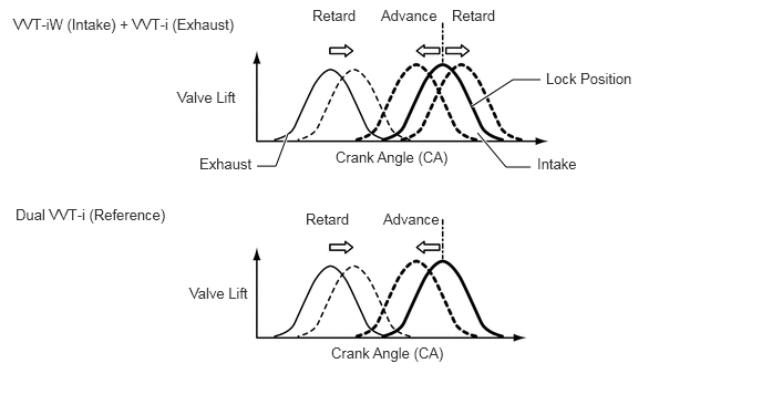
Valve Timing Variable Range
W123161E02
4.49,1.25 4.76,1.573 4.76,1.573 4.99,1.573 true 2.708,1.26 2.594,1.563 2.594,1.563 2.417,1.563 true 4.438,1 4.823,0.75 4.823,0.75 5.083,0.75 true 0.125,0.146 2.573,0.344 2.448,0.198 10 false VVT-iW (Intake) + VVT-i (Exhaust) 0.146,1.938 2.594,2.135 2.448,0.198 10 false Dual VVT-i (Reference) 1.667,0.833 2.521,1.063 0.854,0.229 10 false Valve Lift 1.781,2.677 2.635,2.906 0.854,0.229 10 false Valve Lift 2.938,0.063 3.792,0.292 0.854,0.229 10 false Retard 2.875,1.979 3.615,2.281 0.74,0.302 10 false Retard 3.583,0.063 4.438,0.292 0.854,0.229 10 false Advance 4.25,0.063 5.104,0.292 0.854,0.229 10 false Retard 3.604,1.979 4.448,2.271 0.844,0.292 10 false Advance 5.052,1.458 5.906,1.688 0.854,0.229 10 false Intake 3.156,1.396 4.625,1.646 1.469,0.25 10 false Crank Angle (CA) 3.115,3.24 4.583,3.49 1.469,0.25 10 false Crank Angle (CA) 1.875,1.458 2.729,1.688 0.854,0.229 10 false Exhaust 5.135,0.656 6.104,1.052 0.969,0.396 10 false Lock Position


d.

A timing rotor for the camshaft position sensor is provided on the back of the intake and exhaust camshafts.


e.

The No. 1 valve rocker arm sub-assembly is used as a valve mechanism and by achieving size reduction while drastically reducing the amount of friction that occurs between the sliding parts and cams, low fuel consumption is achieved. Also, an oil pressure type valve lash adjuster assembly is used to make valve clearance adjustment unnecessary in consideration of serviceability.


f.

Together with the use of the No. 1 valve rocker arm sub-assembly, the cam profile has been designed with an indented R (radius). This results in increased valve lift when the valve begins to open and finishes closing, helping to achieve enhanced output performance.


g.

The cam that drives the fuel pump assembly (for high pressure) is positioned directly above the No. 4 cylinder of the exhaust camshaft (No. 2 camshaft) to achieve size reduction. Also, a pump cam with 4 peaks is used in the cam that drives the fuel pump assembly (for high pressure) and by synchronizing fuel pressure-feeding and fuel injection, the difference in fuel pressure between cylinders is reduced.


h.

The vacuum pump assembly is driven by the end of the exhaust camshaft (No. 2 camshaft).


i.

A valve spring (outer compression spring), whose upper portion is shaped like a beehive, is used to reduce inertial mass. As a result, the load on the valve spring (outer compression spring) and friction are reduced.


j.

The diameter of the valve spring retainer has been decreased to reduce inertial mass and friction.


k.

The exhaust valves improve valve cooling performance and reliability by using sodium as a refrigerant. Holes are provided in the valve stems and sodium with high heat conductance and a low melting point is inserted to support high exhaust temperatures. Also, the valve stems are made hollow to achieve weight reduction and reduce friction.
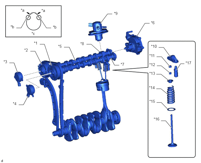
W139475C01
1.438,0.667 1.656,1 1.656,1 1.823,1 true 0.938,0.667 0.75,1 0.75,1 0.583,1 true 3.583,0.833 3.833,0.5 3.833,0.5 4,0.5 true 4.875,1.302 5.167,0.833 5.167,0.833 5.333,0.833 true 3.552,1.854 3.25,1.583 3.25,1.583 3.083,1.583 true 2.688,2.177 2.469,1.688 2.469,1.688 2.281,1.688 true 1.833,2.344 1.583,1.583 1.583,1.583 1.417,1.583 true 1.49,2.313 1.25,1.833 1.25,1.833 1.083,1.833 true 0.625,2.594 0.5,2.25 0.5,2.25 0.333,2.25 true 1,3.438 0.833,3.75 0.833,3.75 0.667,3.75 true 3.948,2.073 4.083,2.333 4.083,2.333 4.25,2.333 true 6.292,2.51 6.438,2.281 6.438,2.281 6.573,2.281 true 6.073,2.031 5.833,1.698 5.833,1.698 5.656,1.698 true 6.052,2.375 5.76,2.031 5.76,2.031 5.583,2.031 true 6.052,2.604 5.75,2.354 5.75,2.354 5.594,2.354 true 6.01,2.875 5.74,2.656 5.74,2.656 5.573,2.656 true 5.969,3.365 5.74,3.177 5.74,3.177 5.573,3.177 true 5.979,3.906 5.75,3.667 5.75,3.667 5.583,3.667 true 6.115,4.573 5.906,4.323 5.906,4.323 5.74,4.323 true 1.208,1.458 1.417,1.646 0.208,0.188 10 false *1 0.865,1.708 1.073,1.885 0.208,0.177 10 false *2 0.125,2.125 0.333,2.302 0.208,0.177 10 false *3 0.458,3.625 0.667,3.813 0.208,0.188 10 false *4 2.073,1.573 2.271,1.76 0.198,0.188 10 false *5 5.385,0.729 5.604,0.896 0.219,0.167 10 false *6 4.302,2.219 4.521,2.406 0.219,0.188 10 false *7 2.865,1.479 3.104,1.646 0.24,0.167 10 false *8 4.063,0.396 4.292,0.583 0.229,0.188 10 false *9 5.385,1.573 5.656,1.76 0.271,0.188 10 false *10 5.323,1.906 5.563,2.104 0.24,0.198 10 false *11 5.323,2.229 5.594,2.406 0.271,0.177 10 false *12 5.323,2.542 5.573,2.729 0.25,0.188 10 false *13 5.313,3.052 5.573,3.25 0.26,0.198 10 false *14 5.323,3.542 5.573,3.74 0.25,0.198 10 false *15 5.479,4.177 5.729,4.365 0.25,0.188 10 false *16 6.615,2.167 6.875,2.365 0.26,0.198 10 false *17 0.74,0.281 0.958,0.479 0.219,0.198 10 false *a 0.375,0.875 0.604,1.052 0.229,0.177 10 false *b 1.125,1.115 1.375,1.313 0.25,0.198 10 false *c 1.479,0.292 1.698,0.49 0.219,0.198 10 false *a 1.885,0.885 2.115,1.063 0.229,0.177 10 false *b
*1 Camshaft Timing Gear Assembly *2 Camshaft Timing Exhaust Gear Assembly
*3 Cam Timing Oil Control Solenoid Assembly (for VVT-i) *4 Cam Timing Oil Control Solenoid Assembly (for VVT-iW)
*5 Exhaust Camshaft (No. 2 Camshaft) *6 Vacuum Pump Assembly
*7 Intake Camshaft (Camshaft) *8 Fuel Pump Assembly (for High Pressure) Driving Cam
*9 Fuel Pump Assembly (for High Pressure) *10 No. 1 Valve Rocker Arm Sub-assembly
*11 Valve Stem Cap *12 Valve Spring Retainer Lock
*13 Valve Spring Retainer *14 Valve Spring (Outer Compression Spring)
*15 Valve Spring Seat *16 Valve
*17 Valve Lash Adjuster Assembly - -
*a Lift Amount Increase *b Indented R Portion of Cam (Profile)
*c Cam with Indented R - -


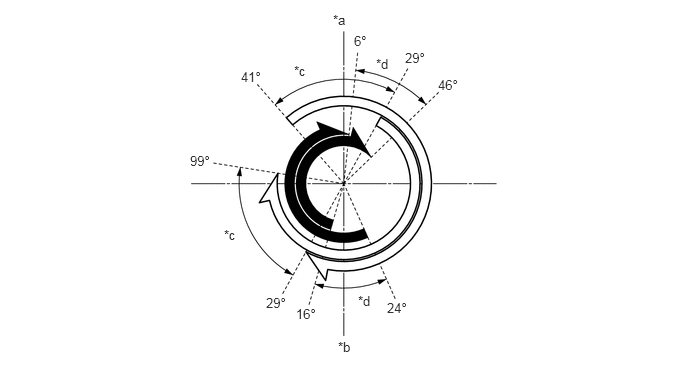
Valve Timing (Models for Europe and Destination Package for Taiwan)
W139476C01
3.469,0.125 3.781,0.281 0.313,0.156 10 false *a 3.521,3.531 3.833,3.688 0.313,0.156 10 false *b 2.333,2.365 2.646,2.521 0.313,0.156 10 false *c 3.729,3.052 4.042,3.208 0.313,0.156 10 false *d 3.688,0.344 4,0.542 0.313,0.198 10 false 6° 3.917,0.583 4.229,0.74 0.313,0.156 10 false *d 3.063,0.656 3.375,0.813 0.313,0.156 10 false *c 4.219,0.521 4.531,0.719 0.313,0.198 10 false 29° 4.563,0.802 4.875,1 0.313,0.198 10 false 46° 4.031,3.125 4.344,3.323 0.313,0.198 10 false 24° 3.083,3.188 3.396,3.385 0.313,0.198 10 false 16° 2.771,3.073 3.083,3.271 0.313,0.198 10 false 29° 1.979,1.594 2.292,1.792 0.313,0.198 10 false 99° 2.51,0.719 2.823,0.917 0.313,0.198 10 false 41°
*a TDC *b BDC
*c VVT-iW Operation Range *d VVT-i Operation Range
V100135

Exhaust Valve Opening Angle
V100136

Intake Valve Opening Angle


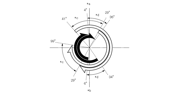
Valve Timing (Except Models for Europe and Destination Package for Taiwan)
W134796C01
2.479,0.688 3.135,0.927 0.656,0.24 10 false 41° 2.99,0.646 3.26,0.865 0.271,0.219 10 false *c 3.365,0.333 3.938,0.573 0.573,0.24 10 false 4° 3.479,0.083 3.771,0.302 0.292,0.219 10 false *a 3.833,0.531 4.042,0.75 0.208,0.219 10 false *d 4.208,0.438 4.833,0.656 0.625,0.219 10 false 29° 4.396,0.615 4.729,0.854 0.333,0.24 10 false 36° 4.365,3.021 4.75,3.229 0.385,0.208 10 false 34° 3.802,3.021 4.094,3.24 0.292,0.219 10 false *d 3.51,3.563 3.781,3.781 0.271,0.219 10 false *b 3.365,3.281 3.771,3.521 0.406,0.24 10 false 6° 2.844,3.156 3.25,3.365 0.406,0.208 10 false 29° 2.406,2.417 2.74,2.604 0.333,0.188 10 false *c 2.031,1.583 2.792,1.792 0.76,0.208 10 false 99°
*a TDC *b BDC
*c VVT-iW Operation Range *d VVT-i Operation Range
V100135

Exhaust Valve Opening Angle
V100136

Intake Valve Opening Angle