Home › Engine / Hybrid System › 8NR-FTS (FUEL) › FUEL SYSTEM › from 2020.08
NM32H0E _51 Engine / Hybrid System _060398 8NR-FTS FUEL _0296169 FUEL SYSTEM DE DETAILS F

8NR-FTS FUEL  FUEL SYSTEM  DETAILS  FUEL PUMP (FOR HIGH PRESSURE)  


CONSTRUCTION


a.

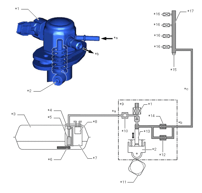
A high efficiency 1-plunger type fuel pump assembly (for high pressure) is used to reduce drive torque.


b.

The fuel pump assembly (for high pressure) consists of the following parts:

i.

A spill control valve which adjusts the discharged amount of high pressure fuel


ii.

A plunger which is driven by the camshaft to pressurize the fuel


iii.

A check valve which mechanically opens and closes the path to the fuel delivery pipe


iv.

A relief valve which leaks fuel when a fuel pressure becomes too high in the high-pressure fuel system


c.

A roller lifter (fuel pump lifter assembly) is used to drive the plunger. As a result, high engine output and high fuel pressure are supported.


d.

The fuel pump assembly (for high pressure) is installed to the camshaft bearing cap via the cylinder head cover sub-assembly and is driven by the cam installed to the exhaust camshaft (No. 2 camshaft).


e.

A fuel pressure pulsation damper is installed inside the fuel pump assembly (for high pressure).


f.

The high pressure fuel pressure is variably controlled between 2.4 and 30 MPa according to driving conditions to reduce friction losses. (Models with No. 2 air fuel ratio sensor)


g.

The high pressure fuel pressure is variably controlled between 2.4 and 20 MPa according to driving conditions to reduce friction losses. (Models with oxygen sensor)


h.

A metal touch taper seal is used for the fuel pipe (for high pressure) fastener.
W126996C02
0.75,0.323 0.99,0.323 0.99,0.323 1.375,0.708 true 1.188,3.24 1.427,3.24 1.427,3.24 1.979,2.906 true 0.615,4.073 0.854,4.073 0.854,4.073 1.073,4.51 true 1.906,3.927 2.156,3.927 2.156,3.927 2.385,4.521 true 1.906,4.188 2.115,4.188 2.115,4.188 2.406,4.927 true 1.906,5.667 2.146,5.667 2.146,5.667 2.375,5.25 true 2.792,5.125 3.104,5.625 3.104,5.625 3.26,5.625 true 2.823,4.656 3.104,4.333 3.104,4.333 3.26,4.333 true 4.427,4.552 4.427,4.115 true 4.521,6.469 4.729,6.469 4.729,6.469 4.917,6.188 true 5.771,5.396 5.771,4.958 true 4.896,4.896 4.969,4.667 4.969,4.667 5.063,4.667 true 5.792,4.417 5.667,4.125 5.667,4.125 5.531,4.125 true 4.969,3.927 5.104,3.708 5.104,3.708 5.219,3.708 true 6.167,2.365 6.167,1.927 true 6.188,0.833 6.385,0.417 6.385,0.417 6.604,0.417 true 5.042,5.313 5.375,5.313 true 0.542,0.24 0.781,0.448 0.24,0.208 10 false *1 0.969,3.156 1.208,3.365 0.24,0.208 10 false *2 0.406,3.979 0.646,4.188 0.24,0.208 10 false *3 1.698,3.844 1.938,4.052 0.24,0.208 10 false *4 1.698,4.094 1.938,4.302 0.24,0.208 10 false *5 1.708,5.594 1.948,5.802 0.24,0.208 10 false *6 3.302,5.542 3.542,5.75 0.24,0.208 10 false *7 3.302,4.25 3.542,4.458 0.24,0.208 10 false *8 4.25,3.625 4.49,3.833 0.24,0.208 10 false *9 4.323,4.583 4.594,4.802 0.271,0.219 10 false *10 4.271,6.396 4.542,6.615 0.271,0.219 10 false *11 5.656,5.427 5.927,5.646 0.271,0.219 10 false *12 5.104,4.594 5.375,4.813 0.271,0.219 10 false *13 5.271,4.042 5.542,4.26 0.271,0.219 10 false *14 5.26,3.625 5.531,3.844 0.271,0.219 10 false *1 6.052,2.406 6.323,2.625 0.271,0.219 10 false *15 5.469,1.583 5.74,1.802 0.271,0.219 10 false *16 5.458,0.427 5.729,0.646 0.271,0.219 10 false *16 5.458,0.802 5.729,1.021 0.271,0.219 10 false *16 5.469,1.188 5.74,1.406 0.271,0.219 10 false *16 6.656,0.323 6.927,0.542 0.271,0.219 10 false *17 4.042,1.271 4.281,1.479 0.24,0.208 10 false *a 3.375,1.844 3.615,2.052 0.24,0.208 10 false *b 6.333,4.281 6.573,4.49 0.24,0.208 10 false *b 3.979,3.875 4.219,4.083 0.24,0.208 10 false *a 6.542,3.083 6.781,3.292 0.24,0.208 10 false *c 5.406,5.229 5.677,5.448 0.271,0.219 10 false *2
*1 Spill Control Valve *2 Roller Lifter (Fuel Pump Lifter Assembly)
*3 Fuel Tank Assembly *4 Fuel Pressure Regulator Assembly
*5 Fuel Pump (for Low Pressure) *6 Fuel Suction Filter
*7 Fuel Suction Tube with Pump and Gauge Assembly *8 Charcoal Canister
*9 Fuel Pump Assembly (for High Pressure) *10 Fuel Pressure Pulsation Damper
*11 Camshaft (Cam to Drive Fuel Pump Assembly (for High Pressure)) *12 Relief Valve
*13 Plunger *14 Check Valve
*15 Fuel Pressure Sensor *16 Fuel Injector Assembly
*17 Fuel Delivery Pipe - -
*a Low-pressure Fuel System (from Fuel Tank Assembly) *b High-pressure Fuel System (to Fuel Delivery Pipe)
*c Pipe of High-pressure Fuel System - -


OPERATION


a.

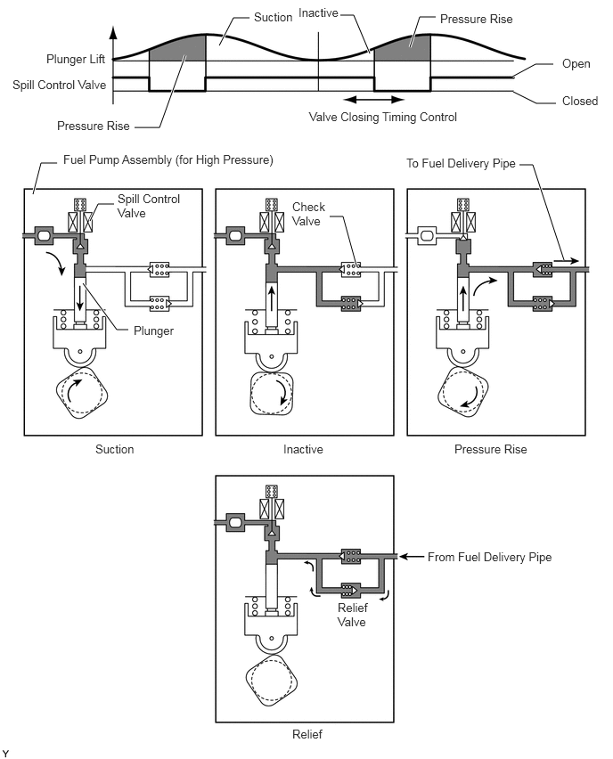
The plunger moves vertically to pressurize the fuel. The fuel is controlled to the necessary fuel pressure by closing the spill control valve, which is installed on the suction side of the fuel pump assembly (for high pressure), at the optimal timing during the compression stroke. When the spill control valve closes at an early timing, the effective stroke of the plunger becomes longer, increasing the fuel pressure.


b.

The fuel, which is pressurized by the plunger and controlled to between 2.4 and 30 MPa, pushes open the check valve and is pressure-fed to the fuel delivery pipe. (Models with No. 2 air fuel ratio sensor)


c.

The fuel, which is pressurized by the plunger and controlled to between 2.4 and 20 MPa, pushes open the check valve and is pressure-fed to the fuel delivery pipe. (Models with oxygen sensor)


d.

The fuel pressure is detected by the fuel pressure sensor installed in the fuel delivery pipe and feedback control is performed by the ECM to control the fuel pressure to the target value.


e.

When a fuel pressure becomes too high in the high-pressure fuel system, the relief valve opens to leak fuel and suppress the fuel pressure to or below the rated working pressure of the system.
W122802E09
2.563,0.531 2.729,0.208 2.729,0.208 2.917,0.208 true 4.323,0.625 4.135,0.177 4.135,0.177 3.979,0.177 true 4.792,0.552 4.906,0.198 4.906,0.198 5.094,0.198 true 0.385,2.271 0.479,1.906 0.479,1.906 0.667,1.906 true 1.052,2.583 1.146,2.385 1.146,2.385 1.333,2.385 true 0.969,3.313 1.365,3.854 1.365,3.854 1.5,3.854 true 6.594,3.042 6.229,1.927 6.229,1.927 6.073,1.927 true 5.99,0.896 6.26,0.75 6.26,0.75 6.469,0.75 true 6,1.073 6.271,1.208 6.271,1.208 6.5,1.208 true 2.167,0.646 1.865,1.49 1.865,1.49 1.573,1.49 true 4.167,3.104 4.01,2.531 4.01,2.531 3.854,2.531 true 0.146,0.906 1.344,1.094 1.198,0.188 10 false Spill Control Valve 0.667,1.385 1.74,1.583 1.073,0.198 10 false Pressure Rise 0.542,0.604 1.688,0.875 1.146,0.271 10 false Plunger Lift 2.969,0.115 3.479,0.385 0.51,0.271 10 false Suction 6.573,0.656 7.083,0.927 0.51,0.271 10 false Open 3.49,0.063 4,0.333 0.51,0.271 10 false Inactive 5.146,0.135 6.115,0.354 0.969,0.219 10 false Pressure Rise 3.615,1.281 5.469,1.5 1.854,0.219 10 false Valve Closing Timing Control 0.74,1.781 3.313,2.01 2.573,0.229 10 false Fuel Pump Assembly (for High Pressure) 1.375,2.24 2.135,2.594 0.76,0.354 10 false Spill Control Valve 3.417,2.333 3.854,2.677 0.438,0.344 10 false Check Valve 1.563,3.781 2.896,4.073 1.333,0.292 10 false Plunger 4.75,1.823 6.146,2.094 1.396,0.271 10 false To Fuel Delivery Pipe 1.115,5.167 1.625,5.438 0.51,0.271 10 false Suction 3.313,5.167 3.823,5.438 0.51,0.271 10 false Inactive 5.313,5.167 6.302,5.385 0.99,0.219 10 false Pressure Rise 5,6.427 6.771,6.813 1.771,0.385 10 false From Fuel Delivery Pipe 3.948,7.021 4.354,7.406 0.406,0.385 10 false Relief Valve 3.417,8.5 4.125,8.76 0.708,0.26 10 false Relief 6.573,1.094 7.083,1.365 0.51,0.271 10 false Closed