RM32H0E
_51
Engine / Hybrid System
_059427
STOP AND START
_0290845
VACUUM SENSOR ASSEMBLY
A
STOP AND START VACUUM SENSOR ASSEMBLY INSTALLATION
PROCEDURE

 1.INSTALL VACUUM SENSOR GROMMET
a.
Install the new vacuum sensor grommet to the brake booster assembly.
2.INSTALL VACUUM SENSOR ASSEMBLY
a.
0.052,0.198 0.292,0.396
0.24,0.198
12
true
*A
0.052,2.51 0.292,2.708
0.24,0.198
12
true
*B
1.583,1.479 1.76,1.667
0.177,0.188
10
true
*a
1.76,3.979 1.958,4.156
0.198,0.177
10
true
*b
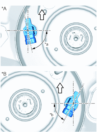
| *A | for LHD |
| *B | for RHD |
| *a | 68° +/- 4° |
| *b | 63° +/- 4° |

|
Upper Side of Vehicle |
Install the vacuum sensor assembly to the brake booster assembly so that the vacuum sensor assembly is angled as shown in the illustration.
b.
Connect the vacuum sensor assembly connector to the vacuum sensor assembly.
3.INSTALL BRAKE MASTER CYLINDER SUB-ASSEMBLY (for LHD)
4.INSTALL BRAKE MASTER CYLINDER SUB-ASSEMBLY (for RHD)