EC6A MANUAL TRANSMISSION / TRANSAXLE MANUAL TRANSAXLE SYSTEM DIAGNOSIS SYSTEM
EURO-OBD (EUROPEAN SPEC)
When troubleshooting Europe On-Board Diagnostic (Euro-OBD) vehicles, an OBD scan tool (complying with ISO 15765-4) must be connected to the vehicle. Various data output from the vehicle's ECM can then be read.

Euro-OBD regulations require that the vehicle's on-board computer illuminate the Malfunction Indicator Lamp (MIL) on the instrument panel when the computer detects a malfunction in any of the following:
The emission control system/components
The powertrain control components (which affect vehicle emissions)
The computer
In addition, the applicable Diagnostic Trouble Codes (DTCs) prescribed by ISO 15765-4 are stored in the ECM memory. If the malfunction does not reoccur in 3 consecutive trips, the MIL turns off automatically but the DTCs remain stored in the ECM memory.
To check for DTCs, connect the GTS or OBD scan tool to the Data Link Connector 3 (DLC3) of the vehicle.
The scan tool displays DTCs, the freeze frame data and a variety of engine data.
The DTCs and freeze frame data can be cleared using the scan tool.
Click hereDrivetrain>EC6A (MANUAL TRANSMISSION / TRANSAXLE)>MANUAL TRANSAXLE SYSTEM>DTC CHECK / CLEAR
M-OBD (EXCEPT EUROPEAN SPEC.)
When troubleshooting Multiplex On-Board Diagnostic (M-OBD) vehicles, the vehicle must be connected to the GTS. Various data output from the ECM can then be read.
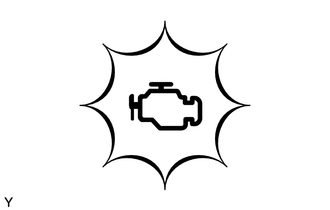
OBD regulations require that the vehicle's onboard computer illuminate the MIL on the instrument panel when the computer detects a malfunction in any of the following:
The emission control system/components
The power train control components (which affect vehicle emissions)
The computer
In addition, the applicable Diagnostic Trouble Codes (DTCs) prescribed by ISO 15765-4 are recorded in the ECM memory.
If the malfunction does not recur in 3 consecutive trips, the MIL goes off automatically but the DTCs remain recorded in the ECM memory.
FUNCTION OF WARNING INDICATOR AND MESSAGE
If the iMT system is not functioning properly, the driver is warned by the iMT warning light or a warning message on the multi-information display in the combination meter assembly.
| DTC | Master Warning Light | iMT Indicator | Warning Message | Detail |
|---|---|---|---|---|
| DTCs are output | Comes on | Does not come on | Displayed | iMT system malfunction |
| DTCs are not output | Does not come on | iMT indicator (Green):
Comes on |
Not displayed | iMT system standby condition |
FREEZE FRAME DATA
The ECM records vehicle and driving condition information as freeze frame data the moment a DTC is stored. When troubleshooting, freeze frame data can be helpful in determining whether the vehicle was moving or stationary, whether the engine was warmed up or not, whether the air fuel ratio was lean or rich, as well as other data stored at the time of a malfunction.
CHECK DATA LINK CONNECTOR 3 (DLC3)
Check the DLC3.
Click hereGeneral>INTRODUCTION>HOW TO TROUBLESHOOT ECU CONTROLLED SYSTEMS>GENERAL INFORMATION
CHECK BATTERY VOLTAGE
- Standard voltage:
11 to 14 V
If the voltage is below 11 V, replace or recharge the battery before proceeding to the next step.