MIRROR (EXT) OUTER REAR VIEW MIRROR GLASS REMOVAL
CAUTION / NOTICE / HINT
- HINT:
- ·
Use the same procedure for the RH side and LH side.
·The following procedure is for the LH side.
PROCEDURE

 87961
1.REMOVE OUTER MIRROR (for LED Type Turn Signal Light)
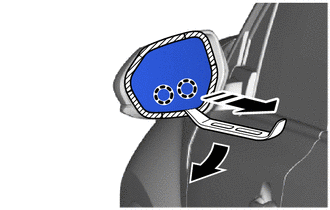

|
Protective Tape |

|
Remove in this Direction |
Apply protective tape to the area as shown in the illustration.
Push the upper part of the mirror surface and tilt it.
Using a moulding remover A, disengage the claws on the lower part of the outer mirror as shown in the illustration.
- NOTICE:
-
Do not push the outer mirror with excessive force. Doing so may cause the actuator to come off or break the mirror surface.
- HINT:
-
If excessive force is used when pressing down the mirror surface, the claws will engage again.
Push the lower part of the mirror surface and tilt it.
- HINT:
-
If excessive force is used when pressing down the mirror surface, the claws will engage again.
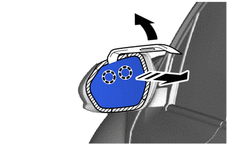
|
|
Protective Tape |
|
|
Remove in this Direction |
Using a moulding remover A, disengage the claws on the upper part of the outer mirror as shown in the illustration.
- NOTICE:
-
Do not push the outer mirror with excessive force. Doing so may cause the actuator to come off or break the mirror surface.
- HINT:
-
If excessive force is used when pressing down the mirror surface, the claws will engage again.
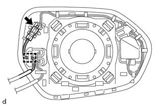
Disengage the guide.
Disconnect the connector.
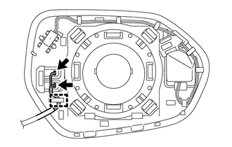
Disengage the guide.
Disconnect the 2 connectors to remove the outer mirror.
87961
2.REMOVE OUTER MIRROR (for Bulb Type Turn Signal Light)
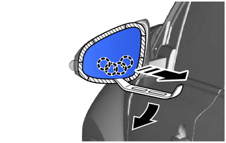
|
|
Protective Tape |
|
|
Remove in this Direction |
Apply protective tape to the area as shown in the illustration.
Push the upper part of the mirror surface and tilt it.
Using a moulding remover A, disengage the claws on the lower part of the outer mirror as shown in the illustration.
- NOTICE:
-
Do not push the outer mirror with excessive force. Doing so may cause the actuator to come off or break the mirror surface.
- HINT:
-
If excessive force is used when pressing down the mirror surface, the claws will engage again.
Push the lower part of the mirror surface and tilt it.
- HINT:
-
If excessive force is used when pressing down the mirror surface, the claws will engage again.
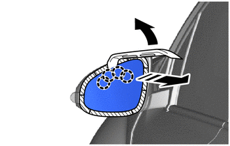
|
|
Protective Tape |
|
|
Remove in this Direction |
Using a moulding remover A, disengage the claws on the upper part of the outer mirror as shown in the illustration.
- NOTICE:
-
Do not push the outer mirror with excessive force. Doing so may cause the actuator to come off or break the mirror surface.
- HINT:
-
If excessive force is used when pressing down the mirror surface, the claws will engage again.
w/ Blind Spot Monitor:
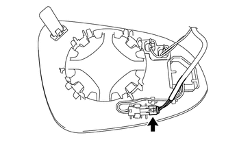
Disconnect the connector.
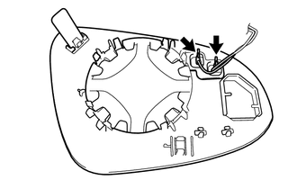
Disconnect the 2 connectors to remove the outer mirror.