HEATING / AIR CONDITIONING BLOWER UNIT(for VALEO Made) REASSEMBLY
CAUTION / NOTICE / HINT
- HINT:
- ·
Use the same procedure for RHD and LHD vehicles.
·The procedure listed below is for LHD vehicles.
PROCEDURE

 87138C
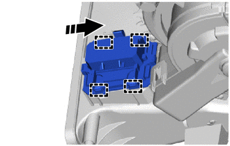
1.INSTALL BLOWER RESISTOR (for Single Type)

|
Install in this Direction |
Engage the guides and install the blower resister as shown in the illustration.
88508C
2.INSTALL AIR FILTER SUB-ASSEMBLY (for Single Type)
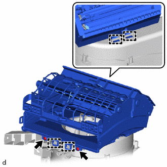
Engage the guides to Install the air filter sub-assembly.
Install the 2 screws.
87130K
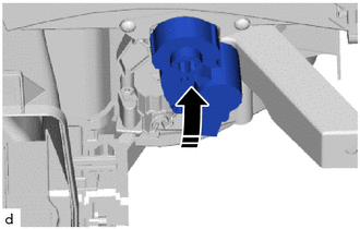
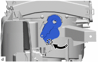
3.INSTALL NO. 1 BLOWER DAMPER SERVO SUB-ASSEMBLY (for Single Type)
|
|
Install in this Direction |
Install the No. 1 blower damper servo sub-assembly as shown in the illustration.
|
|
Install in this Direction |
Turn the No. 1 blower damper servo sub-assembly to engage the claw as shown in the illustration.
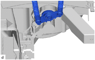
Connect the damper servo link.
87138C
4.INSTALL BLOWER RESISTOR (for Dual Type)
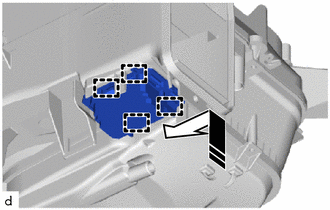
|
|
Install in this Direction |
Engage the guides and install the blower resister as shown in the illustration.
88508C
5.INSTALL AIR FILTER SUB-ASSEMBLY (for Dual Type)
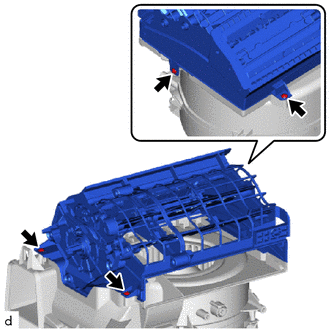
Install the air filter sub-assembly with the 4 screws.
87130K
6.INSTALL NO. 1 BLOWER DAMPER SERVO SUB-ASSEMBLY (for Dual Type)
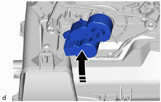
|
|
Install in this Direction |
Install the No. 1 blower damper servo sub-assembly as shown in the illustration.
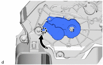
|
|
Install in this Direction |
Turn the No. 1 blower damper servo sub-assembly to engage the claw as shown in the illustration.
87103B
7.INSTALL BLOWER MOTOR WITH FAN SUB-ASSEMBLY (for Single Type)
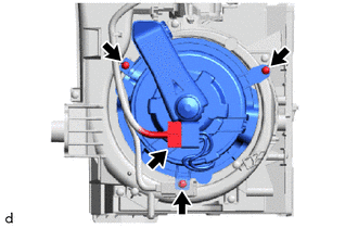
Install the blower motor with fan sub-assembly with the 3 screws.
- NOTICE:
-
Replace the blower motor with fan sub-assembly if it has been dropped or subjected to a severe impact.
Connect the connector.
87139C
8.INSTALL CLEAN AIR FILTER
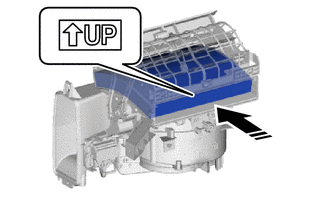
|
|
Install in this Direction |
Install the clean air filter as shown in the illustration.
- NOTICE:
-
Make sure that the "UP" mark is facing the correct direction before installing the clean air filter.
88899M
9.INSTALL AIR FILTER COVER PLATE
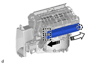
|
|
Install in this Direction (1) |

|
Install in this Direction (2) |
Engage the guide and claw to install the air filter cover plate as shown in the illustration.