INTERIOR PANELS / TRIM REAR CONSOLE BOX INSTALLATION
CAUTION / NOTICE / HINT
- HINT:
- ·
Use the same procedure for LHD and RHD vehicles.
·The procedure listed below is for the LHD vehicles.
PROCEDURE

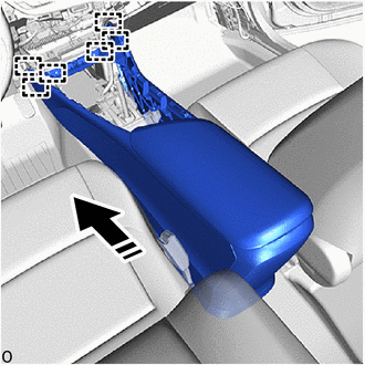
 1.INSTALL REAR CONSOLE BOX ASSEMBLY

|
Install in this Direction |
Engage the guides to install the rear console box assembly as shown in the illustration.
Connect the connector.
Install the 4 bolts.
Install the 4 screws.
58815A
2.INSTALL CONSOLE BOX CARPET
Install the console box carpet.
55619F
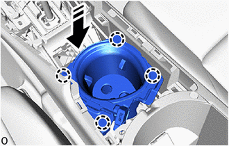
3.INSTALL NO. 2 CONSOLE BOX CUP HOLDER
w/ Illumination:
Connect the connector.
|
|
Install in this Direction |
Engage the claws to install the No. 2 console box cup holder as shown in the illustration.
55618A
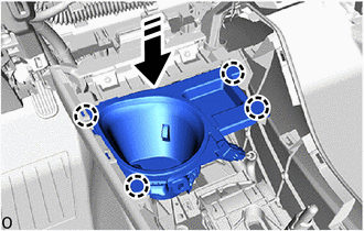
4.INSTALL CONSOLE BOX CUP HOLDER
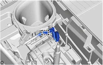
w/ Wire Harness Clamp:
Engage the wire harness clamp.
w/ Illumination:
Connect the connector.
|
|
Install in this Direction |
Engage the claws to install the console box cup holder as shown in the illustration.
58804A
5.INSTALL CONSOLE UPPER PANEL SUB-ASSEMBLY
Connect each connector.
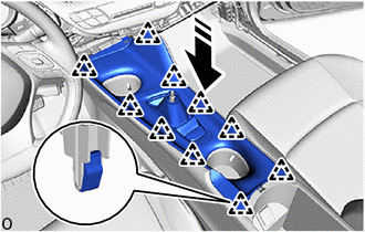
|
|
Install in this Direction |
Engage the clips to install the console upper panel sub-assembly as shown in the illustration.
33504F
6.INSTALL SHIFT LEVER KNOB SUB-ASSEMBLY (for Manual Transaxle)
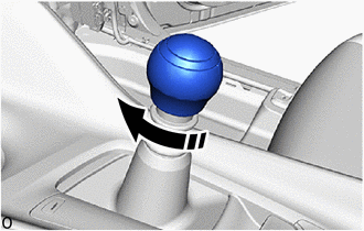
|
|
Install in this Direction |
Turn the shift lever knob sub-assembly as shown in the illustration and install it.
33504F
7.INSTALL SHIFT LEVER KNOB SUB-ASSEMBLY (for CVT)
58817A
8.INSTALL NO. 2 FRONT CONSOLE BOX INSERT
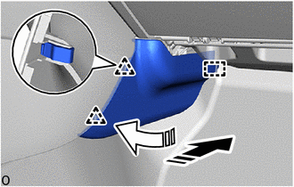
|
|
Install in this Direction (1) |

|
Install in this Direction (2) |
Engage the guide and clips to install the No. 2 front console box insert as shown in the illustration.
58816B
9.INSTALL CONSOLE BOX INSERT
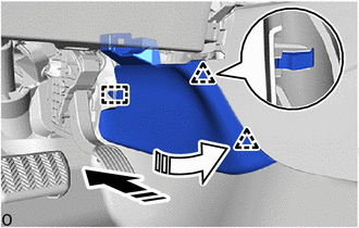
|
|
Install in this Direction (1) |
|
|
Install in this Direction (2) |
Engage the guide and clips to install the console box insert as shown in the illustration.
55440D
10.INSTALL INSTRUMENT PANEL BOX ASSEMBLY
w/ Stereo Jack Adapter:
Connect the connector.
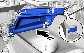
|
|
Install in this Direction |
Engage the claw and clips to install the instrument panel box assembly as shown in the illustration.
55434B
11.INSTALL INSTRUMENT PANEL LOWER CENTER FINISH PANEL
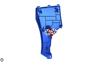
Engage the claws to connect the cooler thermistor.
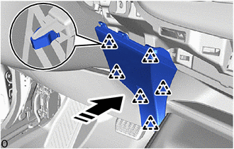
|
|
Install in this Direction |
Engage the clips to install the instrument panel lower center finish panel as shown in the illustration.
55470
12.INSTALL INSTRUMENT CLUSTER FINISH PANEL GARNISH ASSEMBLY
First align clip A, then align clip B.
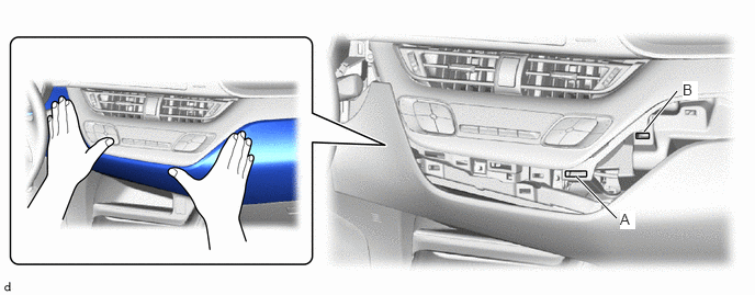
- HINT:
- ·
Do not engage the clips.
·Make sure the clips do not move out of position.
While holding the parts in place so that clip A and clip B do not move out of position, engage the clip on the right side of the instrument cluster finish panel garnish assembly.
- HINT:
-
Press in the clip until it makes a "click" sound.
Press in the clips to engage them in the order shown in the illustration to install the instrument cluster finish panel garnish assembly.
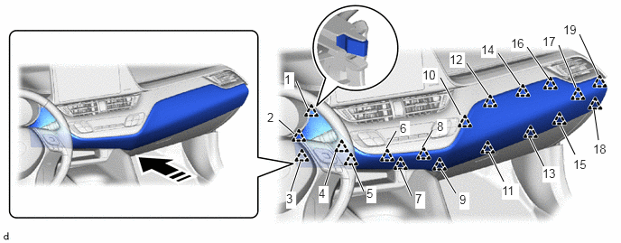
|
|
Install in this Direction | - | - |
- HINT:
- ·
Press in the clip until it makes a "click" sound.
·Check that the instrument cluster finish panel garnish assembly is securely installed and that none of the clips are raised up or not properly engaged.
55606
13.INSTALL NO. 1 INSTRUMENT PANEL UNDER COVER SUB-ASSEMBLY
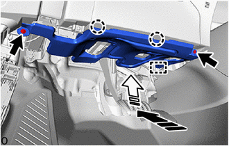
|
|
Install in this Direction (1) |
|
|
Install in this Direction (2) |
Engage the guide and claws to install the No. 1 instrument panel under cover sub-assembly as shown in the illustration.
Install the 2 screws.
62112
14.INSTALL COWL SIDE TRIM BOARD LH
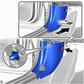
|
|
Install in this Direction (1) |
|
|
Install in this Direction (2) |
Engage the clips to install the cowl side trim board LH as shown in the illustration.
Install the clip.
67914
15.INSTALL FRONT DOOR SCUFF PLATE LH
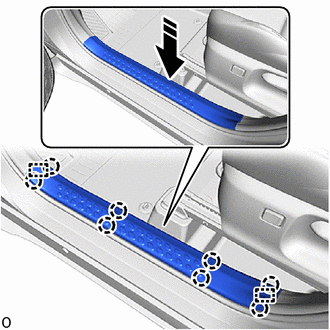
|
|
Install in this Direction |
Engage the claws and guides to install the front door scuff plate LH as shown in the illustration.