RM32H0E
_51
Engine / Hybrid System
_060199
8NR-FTS STARTING
_0295157
IGNITION SWITCH
G
8NR-FTS STARTING IGNITION SWITCH INSPECTION
PROCEDURE

 84450
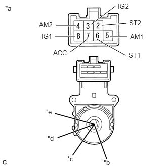
1.INSPECT IGNITION OR STARTER SWITCH ASSEMBLY
a.
1.146,0.531 1.563,0.531
true
1.125,0.75 1.552,0.75
true
1.438,1.073 1.792,0.813
true
2,0.813 2.583,1.135
true
2.271,0.76 2.604,0.76
true
2.094,0.521 2.594,0.479
true
1.875,0.5 2.375,0.125
true
0.104,0.083 0.417,0.24
0.313,0.156
10
false
*a
2.135,3.26 2.448,3.417
0.313,0.156
10
false
*b
1.385,3.188 1.625,3.375
0.24,0.188
10
false
*c
0.979,2.76 1.177,2.979
0.198,0.219
10
false
*d
0.938,2.219 1.177,2.396
0.24,0.177
10
false
*e
1.094,1 1.448,1.198
0.354,0.198
10
false
ACC
0.854,0.667 1.125,0.906
0.271,0.24
10
false
IG1
2.646,1.052 3.104,1.25
0.458,0.198
10
false
ST1
2.677,0.677 3.135,0.875
0.458,0.198
10
false
AM1
0.802,0.427 1.26,0.625
0.458,0.198
10
false
AM2
2.427,0.042 2.885,0.24
0.458,0.198
10
false
IG2
2.656,0.385 3.115,0.583
0.458,0.198
10
false
ST2
| *a | Component without harness connected
(Ignition or Starter Switch Assembly) |
| *b | LOCK |
| *c | ACC |
| *d | ON |
| *e | START |
Check the resistance.
i.
Measure the resistance according to the value(s) in the table below.
- Standard Resistance:
Tester Connection Condition Specified Condition Between all terminals LOCK 10 kΩ or higher 5 (AM1) - 7 (ACC) ACC Below 1 Ω 5 (AM1) - 7 (ACC) - 8 (IG1) ON Below 1 Ω 3 (IG2) - 4 (AM2) 5 (AM1) - 6 (ST1) - 8 (IG1) START Below 1 Ω 2 (ST2) - 3 (IG2) - 4 (AM2)
If the result is not as specified, replace the ignition or starter switch assembly.