Home › Audio / Visual / Telematics › PARK ASSIST / MONITORING › TOYOTA PARKING ASSIST-SENSOR SYSTEM (w/ Simple Intelligent Parking Assist System) › 2016.10–2019.09
RM32H0E _56 Audio / Visual / Telematics _060571 PARK ASSIST / MONITORING _0298265 TOYOTA PARKING ASSIST-SENSOR SYSTEM(w/ Simple Intelligent Parking Assist System) C

PARK ASSIST / MONITORING  TOYOTA PARKING ASSIST-SENSOR SYSTEM(w/ Simple Intelligent Parking Assist System)  C1625  Open or Short in Steering Angle Sensor +B  


DESCRIPTION

This DTC is stored when the clearance warning ECU assembly receives a steering angle sensor power supply malfunction signal via CAN communication from the spiral cable with sensor sub-assembly.

DTC No. Detection Item DTC Detection Condition Trouble Area
C1625 Open or Short in Steering Angle Sensor +B Either condition is met (1 trip detection logic*1):
·

Open in steering angle sensor power source

·

Short in steering angle sensor power source


·

Wire harness or connector

·

Spiral cable with sensor sub-assembly

·

Stop and start system*2


*1: Only output while a malfunction is present.

*2: w/ Stop and Start System


DTC Detection Conditions
Vehicle Condition
Pattern 1 Pattern 2
Diagnosis Condition Ignition switch ON ○ ○
Malfunction Status Open in steering angle sensor power source ○ -
Short in steering angle sensor power source - ○
Detection Time - -
Number of Trips 1 trip 1 trip

HINT:

DTC will be output when conditions for either of the patterns in the table above are met.


WIRING DIAGRAM
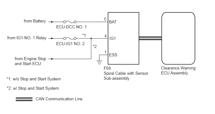
E267876E05
1.115,3.219 2.844,3.479 1.729,0.26 10 false : CAN Communication Line 0.792,0.615 1.688,0.875 0.896,0.26 10 false from Battery 0.24,1.177 1.969,1.438 1.729,0.26 10 false from IG1-NO. 1 Relay 0.49,1.875 1.594,2.24 1.104,0.365 10 false from Engine Stop and Start ECU 1.875,0.813 3.448,1.219 1.573,0.406 10 false ECU-DCC NO. 1 1.875,1.375 2.927,1.656 1.052,0.281 10 false ECU-IG1 NO. 2 2.74,1.094 3,1.354 0.26,0.26 10 false *1 3.094,1.469 3.354,1.729 0.26,0.26 10 false *2 3.635,0.646 3.979,0.906 0.344,0.26 10 false BAT 3.646,1.198 3.99,1.458 0.344,0.26 10 false IG1 3.635,1.75 3.979,2.01 0.344,0.26 10 false ESS 3.469,0.552 3.729,0.813 0.26,0.26 10 false 5 3.479,1.115 3.74,1.375 0.26,0.26 10 false 4 3.479,1.656 3.74,1.917 0.26,0.26 10 false 1 5.365,2.188 6.594,2.552 1.229,0.365 10 false Clearance Warning ECU Assembly 3.458,2.365 5,2.813 1.542,0.448 10 false Spiral Cable with Sensor Sub-assembly 3.458,2.198 3.792,2.438 0.333,0.24 10 false F69 0.219,2.552 2.469,2.833 2.25,0.281 10 false *1: w/o Stop and Start System 0.229,2.865 2.479,3.146 2.25,0.281 10 false *2: w/ Stop and Start System

CAUTION / NOTICE / HINT

NOTICE:
·

Inspect the fuses for circuits related to this system before performing the following procedure.

·

Depending on the parts that are replaced during vehicle inspection or maintenance, performing initialization may be needed. Refer to Calibration.

Click hereAudio / Visual / Telematics>PARK ASSIST / MONITORING>TOYOTA PARKING ASSIST-SENSOR SYSTEM (w/ Simple Intelligent Parking Assist System)>CALIBRATION


PROCEDURE

1.CHECK HARNESS AND CONNECTOR (SPIRAL CABLE WITH SENSOR SUB-ASSEMBLY - BODY GROUND)
a.

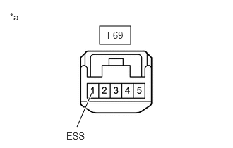
Disconnect the spiral cable with sensor sub-assembly connector.

b.
E360126C01
1.469,0.385 1.927,0.656 0.458,0.271 1.135,1.875 1.354,1.375 true 1.583,0.438 2.042,0.635 0.458,0.198 10 false F69 0.146,0.167 0.604,0.365 0.458,0.198 10 false *a 0.979,1.927 1.438,2.125 0.458,0.198 10 false ESS
*a Front view of wire harness connector
(to Spiral Cable with Sensor Sub-assembly)


Measure the resistance according to the value(s) in the table below.

Standard Resistance:
Tester Connection Condition Specified Condition
F69-1 (ESS) - Body ground Always Below 1 Ω


Result:
Proceed to
OK
NG


OK

2.CHECK HARNESS AND CONNECTOR (SPIRAL CABLE WITH SENSOR SUB-ASSEMBLY BATTERY POWER SUPPLY)

NG

REPAIR OR REPLACE HARNESS OR CONNECTOR

2.CHECK HARNESS AND CONNECTOR (SPIRAL CABLE WITH SENSOR SUB-ASSEMBLY BATTERY POWER SUPPLY)
a.

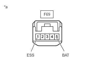
Disconnect the spiral cable with sensor sub-assembly connector.

b.
E360126C03
1.469,0.385 1.927,0.656 0.458,0.271 1.125,1.875 1.344,1.375 true 2.323,1.865 2.052,1.385 true 1.583,0.438 2.042,0.635 0.458,0.198 10 false F69 0.146,0.167 0.604,0.365 0.458,0.198 10 false *a 0.969,1.927 1.427,2.125 0.458,0.198 10 false ESS 2.25,1.927 2.729,2.167 0.479,0.24 10 false BAT
*a Front view of wire harness connector
(to Spiral Cable with Sensor Sub-assembly)


Measure the voltage according to the value(s) in the table below.

Standard Voltage:
Tester Connection Condition Specified Condition
F69-5 (BAT) - F69-1 (ESS) Always 11 to 14 V


Result:
Proceed to
OK
NG


OK

3.CHECK HARNESS AND CONNECTOR (SPIRAL CABLE WITH SENSOR SUB-ASSEMBLY IG POWER SUPPLY)

NG

REPAIR OR REPLACE HARNESS OR CONNECTOR

3.CHECK HARNESS AND CONNECTOR (SPIRAL CABLE WITH SENSOR SUB-ASSEMBLY IG POWER SUPPLY)
a.

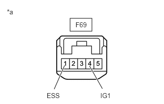
Disconnect the spiral cable with sensor sub-assembly connector.

b.
E360126C04
1.469,0.385 1.927,0.656 0.458,0.271 1.135,1.875 1.354,1.375 true 2.146,1.865 1.875,1.385 true 1.583,0.438 2.042,0.635 0.458,0.198 10 false F69 0.146,0.167 0.604,0.365 0.458,0.198 10 false *a 0.979,1.927 1.438,2.125 0.458,0.198 10 false ESS 2.104,1.927 2.563,2.125 0.458,0.198 10 false IG1

Measure the voltage according to the value(s) in the table below.

Standard Voltage:
Tester Connection Condition Specified Condition
F69-4 (IG1) - F69-1 (ESS) Ignition switch ON 11 to 14 V*1
9.5 to 14 V*2


*1: w/o Stop and Start System

*2: w/ Stop and Start System


Result:
Result Proceed to
OK A
NG (w/o Stop and Start System) B
NG (w/ Stop and Start System) C


A

REPLACE SPIRAL CABLE WITH SENSOR SUB-ASSEMBLY

B

REPAIR OR REPLACE HARNESS OR CONNECTOR

C