3ZR-FAE STARTING STARTER REASSEMBLY
PROCEDURE

 1.INSTALL PLANET CARRIER SHAFT SUB-ASSEMBLY
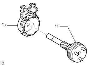
| *1 | Planet Carrier Shaft Sub-assembly |
| *a | Clutch Gear Cover |
Install the planet carrier shaft sub-assembly to the clutch gear cover.
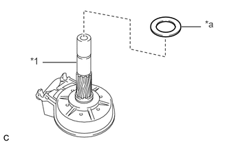
| *1 | Planet Carrier Shaft Sub-assembly |
| *a | Washer |
Install the washer to the planet carrier shaft sub-assembly.
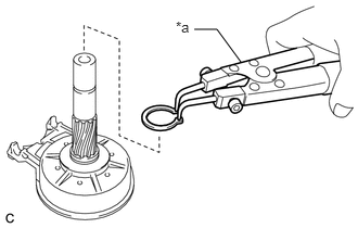
| *a | Snap Ring Pliers |
Using snap ring pliers, install the snap ring to the planet carrier shaft sub-assembly.
2.INSTALL PINION GEAR
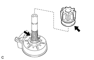

|
High-temperature Grease |
Apply high-temperature grease to the spline of the pinion gear and planet carrier shaft sub-assembly.
Install the pinion gear to the planet carrier shaft sub-assembly.
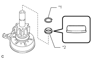
| *1 | Snap Ring |
| *2 | Pinion Stop Collar |
Install the pinion stop collar and a new snap ring to the planet carrier shaft sub-assembly.
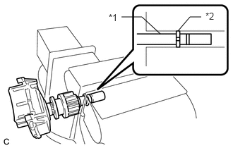
| *1 | Planet Carrier Shaft Sub-assembly |
| *2 | Snap Ring |
Using a vise, compress the snap ring.
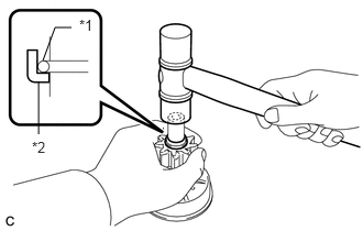
| *1 | Snap Ring |
| *2 | Pinion Stop Collar |
While holding the pinion gear, lightly tap the planet carrier shaft sub-assembly and install the pinion stop collar onto the snap ring with a plastic hammer.
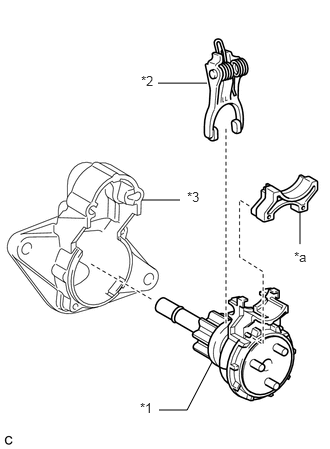
| *1 | Planet Carrier Shaft Sub-assembly with Pinion Gear |
| *2 | Pinion Drive Lever |
| *3 | Starter Drive Housing Assembly |
| *a | Starter Drive Housing Cover |
Install the planet carrier shaft sub-assembly with pinion gear, pinion drive lever and starter drive housing cover to the starter drive housing assembly.
28150
3.INSTALL MAGNET STARTER SWITCH ASSEMBLY
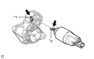
| *1 | Pinion Drive Lever |
| *a | Hook |
|
|
High-temperature Grease |
Apply high-temperature grease to the hook and pinion drive lever.
Hang the hook of the magnet starter switch assembly on the pinion drive lever.
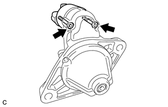
Using a T25 "TORX" socket wrench, install the magnet starter switch assembly with the 2 screws.
- Torque:
- 6.5 N*m (66 kgf*cm, 58 in.*lbf)
28160
4.INSTALL STARTER ARMATURE ASSEMBLY
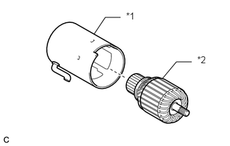
| *1 | Starter Yoke Assembly |
| *2 | Starter Armature Assembly |
Install the starter armature assembly to the starter yoke assembly.
5.INSTALL RING GEAR
|
|
High-temperature Grease |
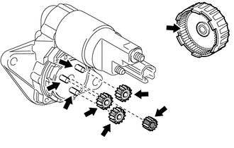
Apply high-temperature grease to the sun gear, 3 planetary gears, 3 planetary gear shafts and ring gear.
Install the sun gear and 3 planetary gears to the planet carrier shaft sub-assembly.
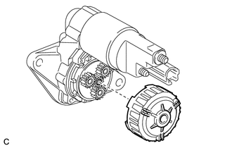
Install the ring gear to the starter drive housing assembly.
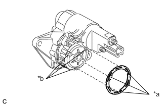
| *a | Groove |
| *b | Protrusion |
Install the starter armature ring to the ring gear as shown in the illustration.
- NOTICE:
-
Align the grooves of the starter armature ring with the protrusions of the ring gear when installing.
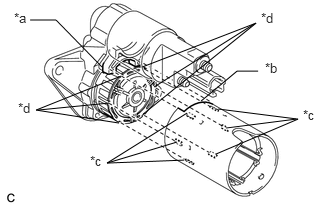
| *a | Starter Drive Housing Cover |
| *b | Cutout |
| *c | Protrusion |
| *d | Groove |
Install the starter yoke assembly to the starter drive housing assembly.
- NOTICE:
- ·
Align the cutout of the starter yoke assembly with the starter drive housing cover.
·Align the protrusions of the starter yoke assembly with the grooves of the starter armature ring and ring gear when installing.
28140
6.INSTALL STARTER BRUSH HOLDER ASSEMBLY
Secure the starter assembly in a vise between aluminum plates.
- NOTICE:
-
Do not overtighten the vise.
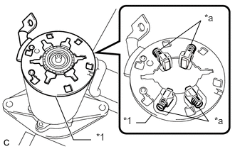
| *1 | Starter Brush Holder Assembly |
| *a | Spring |
While compressing the springs, install the starter brush holder assembly to the starter armature assembly.
7.INSTALL STARTER COMMUTATOR END FRAME ASSEMBLY
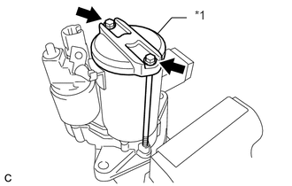
| *1 | Starter Commutator End Frame Assembly |
Install the starter commutator end frame assembly to the starter yoke assembly with the 2 through bolts.
- Torque:
- 5.0 N*m (51 kgf*cm, 44 in.*lbf)
Remove the starter assembly from the vise.
Connect the field coil lead wire to the magnet starter switch assembly with the nut.
- Torque:
- 5.0 N*m (51 kgf*cm, 44 in.*lbf)