8NR-FTS STARTING STARTER(for Valeo Made except Cold Area Specification Vehicles) REASSEMBLY
PROCEDURE

 28021
1.INSTALL STARTER CENTER BEARING CLUTCH SUB-ASSEMBLY
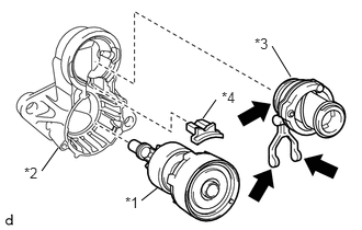
| *1 | Starter Center Bearing Clutch Sub-assembly |
| *2 | Starter Drive Housing Assembly |
| *3 | Pinion Drive Lever |
| *4 | Plastic Seal |

|
High-temperature Grease |
Apply high-temperature grease to the pinion drive lever as shown in the illustration.
- HINT:
-
Apply a total of approximately 0.1 g (0.00352 oz) of high-temperature grease to the pinion drive lever.
Install the pinion drive lever and plastic seal to the starter center bearing clutch sub-assembly.
Install the starter center bearing clutch sub-assembly together with the pinion drive lever and plastic seal to the starter drive housing assembly.
28160
2.INSTALL STARTER ARMATURE ASSEMBLY
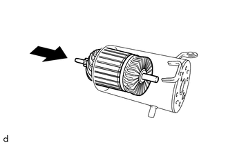
Install the starter armature assembly to the starter yoke assembly.
28130
3.INSTALL STARTER COMMUTATOR END FRAME ASSEMBLY
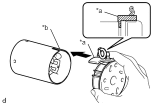
| *a | Rubber Part |
| *b | Groove |
Install the starter commutator end frame assembly to the starter yoke assembly.
- NOTICE:
-
Align the field coil lead wire rubber of the starter yoke assembly with the cutout of the starter commutator end frame assembly.
28120
4.INSTALL STARTER YOKE ASSEMBLY
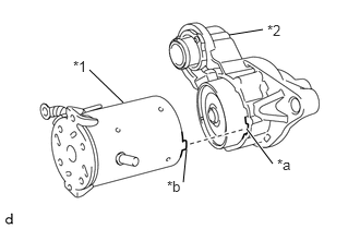
| *1 | Starter Yoke Assembly |
| *2 | Starter Drive Housing Assembly |
| *a | Cutout |
| *b | Protrusion |
Align the claw of the starter yoke assembly with the groove inside the starter drive housing assembly.
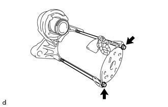
Install the starter yoke assembly with the 2 through bolts.
- Torque:
- 6.4 N*m (65 kgf*cm, 57 in.*lbf)
28150
5.INSTALL MAGNET STARTER SWITCH ASSEMBLY
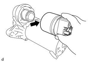
|
|
High-temperature Grease |
Apply high-temperature grease to the magnet starter switch assembly as shown in the illustration.
- HINT:
-
Apply a total of approximately 0.3 g (0.0105 oz) of high-temperature grease to the magnet starter switch assembly.
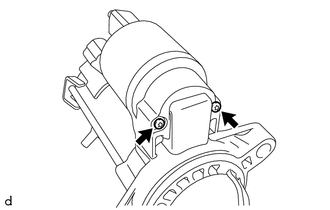
Using a T20 "TORX" socket wrench, Install the magnet starter switch assembly with the 2 bolts.
- Torque:
- 3.6 N*m (37 kgf*cm, 32 in.*lbf)
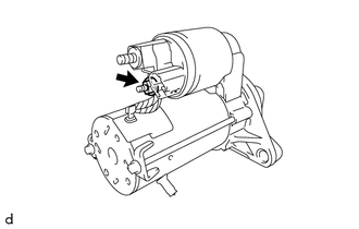
Connect the lead wire to terminal C with the nut.
- Torque:
- 9.5 N*m (97 kgf*cm, 84 in.*lbf)