INTERIOR PANELS / TRIM REAR CONSOLE BOX REMOVAL
CAUTION / NOTICE / HINT
- HINT:
- ·
Use the same procedure for LHD and RHD vehicles.
·The procedure listed below is for the LHD vehicles.
PROCEDURE

 67914
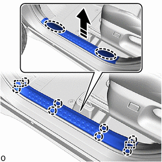
1.REMOVE FRONT DOOR SCUFF PLATE LH

|
Place Hands Here |

|
Remove in this Direction |
Disengage the claws and guides to remove the front door scuff plate LH as shown in the illustration.
62112
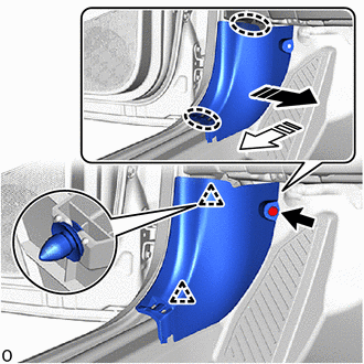
2.REMOVE COWL SIDE TRIM BOARD LH
|
|
Place Hands Here |
|
|
Remove in this Direction |
Remove the clip.
Disengage the clips to remove the cowl side trim board LH as shown in the illustration.
55606
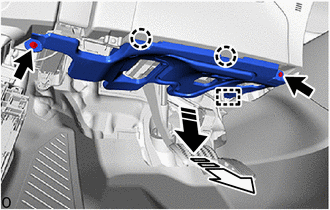
3.REMOVE NO. 1 INSTRUMENT PANEL UNDER COVER SUB-ASSEMBLY
|
|
Remove in this Direction (1) |

|
Remove in this Direction (2) |
Remove the 2 screws.
Disengage the claws and guide to remove the No. 1 instrument panel under cover sub-assembly as shown in the illustration.
55470
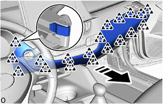
4.REMOVE INSTRUMENT CLUSTER FINISH PANEL GARNISH ASSEMBLY
|
|
Remove in this Direction |
Disengage the clips to remove the instrument cluster finish panel garnish assembly as shown in the illustration.
55434B
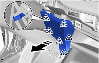
5.REMOVE INSTRUMENT PANEL LOWER CENTER FINISH PANEL
|
|
Remove in this Direction |
Disengage the clips to remove the instrument panel lower center finish panel as shown in the illustration.
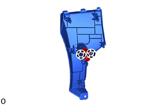
Disengage the claws to disconnect the cooler thermistor.
55440D
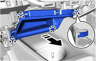
6.REMOVE INSTRUMENT PANEL BOX ASSEMBLY
|
|
Remove in this Direction |
Disengage the clips and claw to remove the instrument panel box assembly as shown in the illustration.
w/ Stereo Jack Adapter:
Disconnect the connector.
Disengage the clamp to disconnect the antenna cord sub-assembly.
58816B
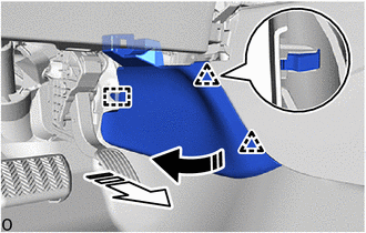
7.REMOVE CONSOLE BOX INSERT
|
|
Remove in this Direction (1) |
|
|
Remove in this Direction (2) |
Disengage the clips and guide to remove the console box insert as shown in the illustration.
58817A
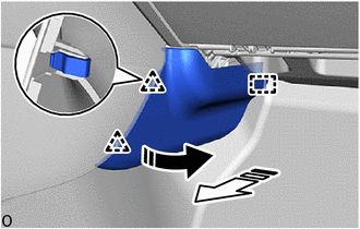
8.REMOVE NO. 2 FRONT CONSOLE BOX INSERT
|
|
Remove in this Direction (1) |
|
|
Remove in this Direction (2) |
Disengage the clips and guide to remove the No. 2 front console box insert as shown in the illustration.
33504F
9.REMOVE SHIFT LEVER KNOB SUB-ASSEMBLY (for CVT)
33504F
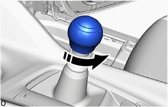
10.REMOVE SHIFT LEVER KNOB SUB-ASSEMBLY (for Manual Transaxle)
|
|
Remove in this Direction |
Turn the shift lever knob sub-assembly as shown in the illustration and remove it.
58804A
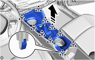
11.REMOVE CONSOLE UPPER PANEL SUB-ASSEMBLY
|
|
Remove in this Direction |
Disengage the clips to remove the console upper panel sub-assembly as shown in the illustration.
Disconnect each connector.
55618A
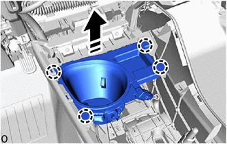
12.REMOVE CONSOLE BOX CUP HOLDER
|
|
Remove in this Direction |
Disengage the claws to remove the console box cup holder as shown in the illustration.
w/ Illumination:
Disconnect the connector.
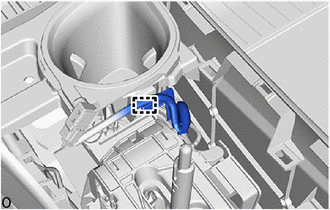
w/ Wire Harness Clamp:
Using a clip remover, disengage the wire harness clamp.
55619F
13.REMOVE NO. 2 CONSOLE BOX CUP HOLDER
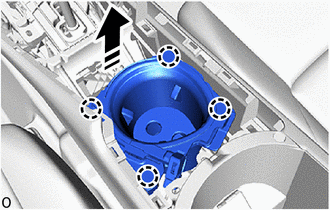
|
|
Remove in this Direction |
Disengage the claws to remove the No. 2 console box cup holder as shown in the illustration.
w/ Illumination:
Disconnect the connector.
58815A
14.REMOVE CONSOLE BOX CARPET
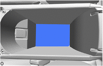
Remove the console box carpet.
15.REMOVE REAR CONSOLE BOX ASSEMBLY
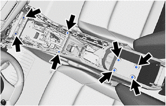
Remove the 4 screws.
Remove the 4 bolts.
Disconnect the connector.
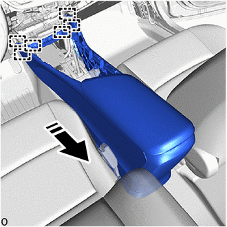
|
|
Remove in this Direction |
Disengage the guides to remove the rear console box assembly as shown in the illustration.
86190C
16.REMOVE NO. 1 STEREO JACK ADAPTER ASSEMBLY (w/ USB Port)
- HINT:
-
Perform this procedure only when replacement of the instrument panel box assembly is necessary.
-
Click hereAudio / Visual / Telematics>AUDIO / VIDEO>STEREO JACK ADAPTER ASSEMBLY>REMOVAL