RM32H0E
_55
Steering
_059604
STEERING COLUMN
_0292298
STEERING PAD SWITCH
G
STEERING COLUMN STEERING PAD SWITCH INSPECTION
PROCEDURE

 84250A
1.INSPECT STEERING PAD SWITCH ASSEMBLY
a.
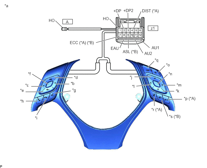
for Type A:
i.
Measure the resistance according to the value(s) in the table below.
2.167,0.667 2.51,0.833
0.344,0.167
5.125,0.896 5.469,1.063
0.344,0.167
2.177,0.969 1.917,0.719
false
4.115,1 3.792,0.656
true
4.281,1 4.073,0.469
true
4.438,0.99 4.427,0.448
true
4.615,1 4.885,0.396
true
5.177,1.656 4.729,1.26
true
4.948,1.844 4.594,1.25
true
4.448,1.677 4.438,1.26
true
4.146,1.667 4.323,1.281
true
3.323,1.479 4.135,1.26
true
1.677,2.927 1.115,2.573
true
1.479,3 1.083,3
true
1.5,3.188 0.885,3.188
true
2.51,2.698 1.896,2.698
true
2.396,2.917 1.927,2.917
true
2.448,3.156 1.885,3.24
true
1.271,3.99 1.594,3.448
true
1.292,3.51 0.896,3.51
true
5.333,2.125 5.104,2.354
true
5.708,2.281 5.479,2.51
true
5.802,2.583 5.458,2.917
true
5.229,2.667 4.656,2.667
true
5.229,2.938 4.719,2.99
true
5.333,3.354 5.344,3.677
true
5.594,3.479 5.813,4.042
true
6.302,3.448 5.833,3.448
true
6.063,2.958 5.667,2.958
true
6.031,3.167 5.635,3.167
true
0.156,0.115 0.469,0.271
0.313,0.156
10
false
*a
2.448,2.813 2.76,2.969
0.313,0.156
10
false
*b
0.875,2.875 1.188,3.031
0.313,0.156
10
false
*c
2.563,2.604 2.875,2.76
0.313,0.156
10
false
*d
0.698,3.052 1.01,3.208
0.313,0.156
10
false
*e
0.969,2.479 1.281,2.635
0.313,0.156
10
false
*f
2.5,3.042 3.021,3.323
0.521,0.281
10
false
*g
0.698,3.427 0.979,3.646
0.281,0.219
10
false
*h
4.49,2.594 5.01,2.813
0.521,0.219
10
false
*j
6.083,3.073 6.396,3.229
0.313,0.156
10
false
*k
4.573,2.917 4.885,3.073
0.313,0.156
10
false
*l
6.115,2.865 6.427,3.021
0.313,0.156
10
false
*m
5.833,2.479 6.146,2.635
0.313,0.156
10
false
*n
5.75,2.167 6.063,2.323
0.313,0.156
10
false
*o
6.365,3.333 6.854,3.646
0.49,0.313
10
false
*p (*A)
5.354,2 5.583,2.229
0.229,0.229
10
false
*q
5.24,3.719 5.688,3.958
0.448,0.24
10
false
*r (*A)
5.854,3.958 6.354,4.229
0.5,0.271
10
false
*s (*B)
1.688,0.625 2.01,0.792
0.323,0.167
10
false
HO
2.281,0.677 2.479,0.854
0.198,0.177
10
false
A
5.219,0.896 5.531,1.094
0.313,0.198
10
false
z1
3.563,0.563 3.885,0.729
0.323,0.167
10
false
HO
3.927,0.292 4.25,0.458
0.323,0.167
10
false
+DP
4.271,0.281 4.708,0.448
0.438,0.167
10
false
+DP2
4.917,0.292 5.635,0.542
0.719,0.25
10
false
DIST (*A)
5.25,1.573 5.906,1.75
0.656,0.177
10
false
AU1
5,1.771 5.656,1.948
0.656,0.177
10
false
AU2
4.25,1.708 4.865,1.969
0.615,0.26
10
false
ASL (*B)
3.833,1.594 4.292,1.792
0.458,0.198
10
false
EAU
2.417,1.396 3.385,1.625
0.969,0.229
10
false
ECC (*A) (*B)
1.208,4.01 1.469,4.198
0.26,0.188
10
false
*i
| *A | w/ Lane Departure Alert System | *B | w/ Speed Limiter System |
| *a | Component without harness connected
(Steering Pad Switch Assembly) |
*b | Seek+ |
| *c | Seek- | *d | Volume+ |
| *e | Volume- | *f | MODE |
| *g | Voice | *h | Off Hook |
| *i | On Hook | *j | Up |
| *k | Down | *l | Left |
| *m | Right | *n | Enter |
| *o | Back | *p | Distance Control |
| *q | TRIP | *r | Lane Departure Alert |
| *s | Speed Limiter | - | - |
- Standard Resistance:
Tester Connection Condition Specified Condition z1-11 (AU1) - z1-8 (EAU) No switch pushed 95 to 105 kΩ Seek+ switch pushed Below 2.5 Ω Seek- switch pushed 313 to 345 Ω Volume+ switch pushed 950 to 1050 Ω Volume- switch pushed 2955 to 3265 Ω z1-10 (AU2) - z1-8 (EAU) No switch pushed 95 to 105 kΩ MODE switch pushed Below 2.5 Ω On hook switch pushed 313 to 345 Ω Off hook switch pushed 950 to 1050 Ω Voice switch pushed 2955 to 3265 Ω z1-3 (+DP2) - z1-8 (EAU) No switch pushed 95 to 105 kΩ Left switch pushed Below 2.5 Ω Up switch pushed 313 to 345 Ω Down switch pushed 950 to 1050 Ω Right switch pushed 2955 to 3265 Ω z1-2 (+DP) - z1-8 (EAU) No switch pushed 95 to 105 kΩ Enter switch pushed Below 2.5 Ω TRIP switch pushed 313 to 345 Ω Back switch pushed 950 to 1050 Ω z1-4 (DIST) - z1-7 (ECC)*1 No switch pushed 1 MΩ or higher Distance control switch pushed Below 2.5 Ω Lane departure alert switch pushed 228 to 252 Ω z1-9 (ASL) - z1-7 (ECC)*2 No switch pushed 1 MΩ or higher Speed limiter switch pushed Below 2.5 Ω z1-1 (HO) - A-1(HO) Always Below 2.5 Ω
*1: w/ Lane Departure Alert System
*2: w/ Speed Limiter System
If the result is not as specified, replace the steering pad switch assembly.
b.
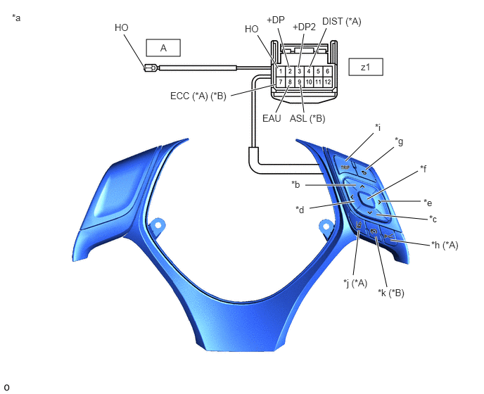
for Type B:
i.
Measure the resistance according to the value(s) in the table below.
2.167,0.583 2.667,0.833
0.5,0.25
5.167,0.865 5.667,1.115
0.5,0.25
5.115,2.385 5.531,1.969
true
5.417,2.51 5.833,2.177
true
5.438,2.948 6.188,2.531
true
5.646,2.979 6.229,2.979
true
5.573,3.177 6.333,3.25
true
5.781,3.552 6.365,3.635
true
5.729,4.25 5.563,3.5
true
5.229,4.073 5.313,3.406
true
3.417,1.417 4.083,1.25
true
4.083,1.667 4.281,1.26
true
4.5,1.667 4.448,1.25
true
4.115,1.01 3.813,0.521
true
4.281,1 4.115,0.417
true
4.417,1 4.5,0.5
true
4.583,1 4.833,0.417
true
2.135,1 1.833,0.51
true
4.521,2.74 5.271,2.74
true
4.583,3.083 5.25,2.979
true
2.375,0.625 2.625,0.865
0.25,0.24
10
false
A
5.344,0.906 5.594,1.094
0.25,0.188
10
false
z1
0.177,0.177 0.49,0.333
0.313,0.156
10
false
*a
4.313,2.646 4.625,2.802
0.313,0.156
10
false
*b
6.354,3.156 6.667,3.313
0.313,0.156
10
false
*c
4.375,3.021 4.688,3.177
0.313,0.156
10
false
*d
6.271,2.917 6.583,3.073
0.313,0.156
10
false
*e
6.219,2.417 6.531,2.573
0.313,0.156
10
false
*f
5.844,2 6.156,2.229
0.313,0.229
10
false
*g
6.385,3.542 6.865,3.729
0.479,0.188
10
false
*h (*A)
5.552,1.802 5.865,1.958
0.313,0.156
10
false
*i
5.083,4.104 5.531,4.333
0.448,0.229
10
false
*j (*A)
5.594,4.25 6.073,4.469
0.479,0.219
10
false
*k (*B)
3.625,0.344 3.938,0.542
0.313,0.198
10
false
HO
3.948,0.208 4.271,0.417
0.323,0.208
10
false
+DP
4.333,0.313 4.74,0.51
0.406,0.198
10
false
+DP2
4.771,0.229 5.438,0.438
0.667,0.208
10
false
DIST (*A)
3.885,1.667 4.271,1.885
0.385,0.219
10
false
EAU
4.292,1.667 4.885,1.896
0.594,0.229
10
false
ASL (*B)
2.521,1.333 3.5,1.573
0.979,0.24
10
false
ECC (*A) (*B)
1.698,0.323 2.01,0.521
0.313,0.198
10
false
HO
| *A | w/ Lane Departure Alert System | *B | w/ Speed Limiter System |
| *a | Component without harness connected
(Steering Pad Switch Assembly) |
*b | Up |
| *c | Down | *d | Left |
| *e | Right | *f | Enter |
| *g | Back | *h | Distance Control |
| *i | TRIP | *j | Lane Departure Alert |
| *k | Speed Limiter | - | - |
- Standard Resistance:
Tester Connection Condition Specified Condition z1-3 (+DP2) - z1-8 (EAU) No switch pushed 95 to 105 kΩ Left switch pushed Below 2.5 Ω Up switch pushed 313 to 345 Ω Down switch pushed 950 to 1050 Ω Right switch pushed 2955 to 3265 Ω z1-2 (+DP) - z1-8 (EAU) No switch pushed 95 to 105 kΩ Enter switch pushed Below 2.5 Ω TRIP switch pushed 313 to 345 Ω Back switch pushed 950 to 1050 Ω z1-4 (DIST) - z1-7 (ECC)*1 No switch pushed 1 MΩ or higher Distance control switch pushed Below 2.5 Ω Lane departure alert switch pushed 228 to 252 Ω z1-9 (ASL) - z1-7 (ECC)*2 No switch pushed 1 MΩ or higher Speed limiter switch pushed Below 2.5 Ω z1-1 (HO) - A-1(HO) Always Below 2.5 Ω
*1: w/ Lane Departure Alert System
*2: w/ Speed Limiter System
If the result is not as specified, replace the steering pad switch assembly.
c.
1.906,1.198 1.583,0.542
true
2.167,1.188 2.49,0.521
true
0.156,0.146 0.469,0.344
0.313,0.198
10
false
*a
1.25,0.448 1.604,0.635
0.354,0.188
10
false
IL+2
2.563,0.448 2.917,0.635
0.354,0.188
10
false
IL-2
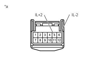
| *a | Component without harness connected
(Steering Pad Switch Assembly) |
Check that the illumination illuminates.
i.
Apply battery voltage between the terminals of the switch, and check the illumination condition of the steering pad switch assembly.
- Standard:
Measurement Condition Specified Condition Battery positive (+) → 5 (IL+2)
Battery negative (-) → 6 (IL-2)Illuminates
If the result is not as specified, replace the steering pad switch assembly.