EXTERIOR PANELS / TRIM REAR BUMPER REMOVAL
CAUTION / NOTICE / HINT
The necessary procedures (adjustment, calibration, initialization or registration) that must be performed after parts are removed and installed, or replaced during the rear bumper assembly removal/installation are shown below.
| Replaced Part or Performed Procedure | Necessary Procedure | Effect/Inoperative Function when Necessary Procedure not Performed | Link |
|---|---|---|---|
| Rear bumper assembly | ·
Measurement of ultrasonic sensor detection angle ·
Ultrasonic sensor detection angle registration |
·
Parking support brake system ·
Simple intelligent parking assist system |
( ) |
- HINT:
-
If the bumper is damaged, there is a possibility that the installation area of the blind spot monitor sensor may be deformed and the blind spot monitor system may not operate correctly, so visually inspect the blind spot monitor sensor installation area (frame, stud bolt) to make sure it is not dented or bent.
-
Click hereAudio / Visual / Telematics>PARK ASSIST / MONITORING>BLIND SPOT MONITOR SYSTEM>OPERATION CHECK
-
If the visual inspection finds a problem, check the installation condition of the blind spot monitor sensor, and adjust the installation position of the blind spot monitor sensor as necessary.
PROCEDURE

 52592
1.REMOVE REAR BUMPER SIDE SEAL LH
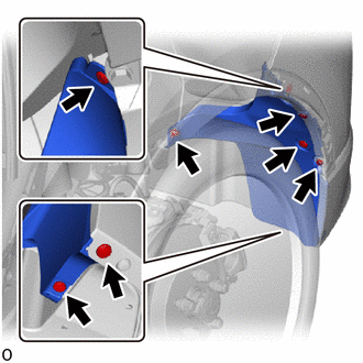
Remove the 7 clips and rear bumper side seal LH.
52591
2.REMOVE REAR BUMPER SIDE SEAL RH
- HINT:
-
Use the same procedure as for the LH side.
75606B
3.SEPARATE QUARTER OUTSIDE MOULDING SUB-ASSEMBLY LH
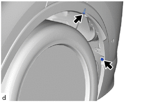
Remove the 2 screws.
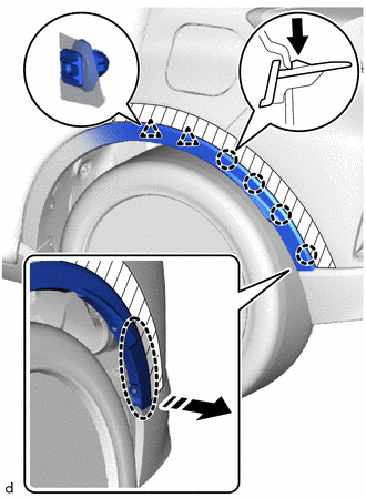

|
Protective Tape |

|
Push |

|
Place Hand Here |

|
Remove in this Direction |
Apply protective tape around the quarter outside moulding LH.
Disengage the claws by pushing the area indicated by the arrow in the illustration with a finger.
- NOTICE:
-
To avoid damaging the claws, do not forcibly pull the quarter outside moulding LH.
Disengage the clip to disconnect the quarter outside moulding sub-assembly LH from the rear bumper assembly.
75605B
4.SEPARATE QUARTER OUTSIDE MOULDING SUB-ASSEMBLY RH
- HINT:
-
Use the same procedure as for the LH side.
5.REMOVE REAR BUMPER ASSEMBLY
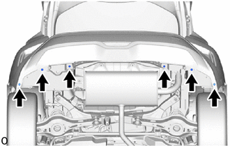
Remove the 6 clips.
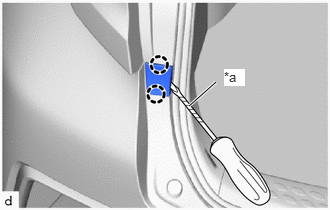
| *a | Protective Tape |
Using a screwdriver with its tip wrapped in protective tape, disengage the claws to open the rear bumper upper cover LH.
- HINT:
-
Use the same procedure for the RH side and LH side.
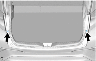
Remove the 2 bolts.
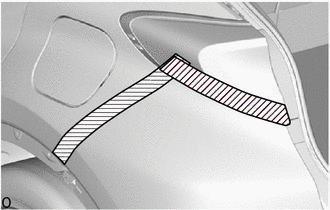
|
|
Protective Tape |
Apply protective tape around the rear bumper assembly.
- HINT:
-
Use the same procedure for the RH side and LH side.
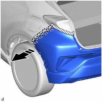
|
|
Remove in this Direction |
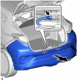
Disengage the claws as shown in the illustration.
- HINT:
-
Use the same procedure for the RH side and LH side.
|
|
Remove in this Direction |
Disengage the claws as shown in the illustration.
w/ Wire Harness:
Disconnect the connector.
Remove the rear bumper assembly.