Home › Audio / Visual / Telematics › PARK ASSIST / MONITORING › TOYOTA PARKING ASSIST-SENSOR SYSTEM › from 2019.09
RM32H0E _56 Audio / Visual / Telematics _060571 PARK ASSIST / MONITORING _0407351 TOYOTA PARKING ASSIST-SENSOR SYSTEM J

PARK ASSIST / MONITORING  TOYOTA PARKING ASSIST-SENSOR SYSTEM  Buzzer does not Sound  


WIRING DIAGRAM
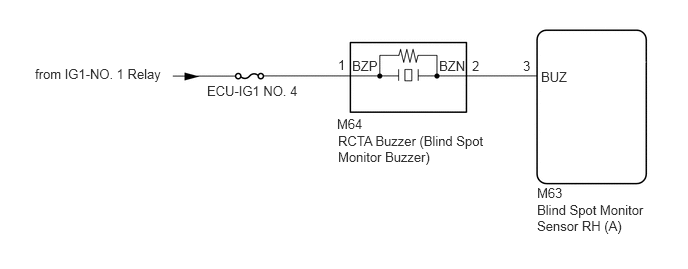
E427339E04
0.365,0.688 3.427,0.885 3.063,0.198 10 false from IG1-NO. 1 Relay 2.156,0.865 3.24,1.094 1.083,0.229 10 false ECU-IG1 NO. 4 3.51,1.208 3.969,1.406 0.458,0.198 10 false M64 3.521,1.385 5.104,1.906 1.583,0.521 10 false RCTA Buzzer (Blind Spot Monitor Buzzer) 3.667,0.604 4.125,0.802 0.458,0.198 10 false BZP 3.521,0.594 3.677,0.792 0.156,0.198 10 false 1 4.573,0.604 5.031,0.802 0.458,0.198 10 false BZN 4.917,0.604 5.073,0.802 0.156,0.198 10 false 2 5.448,0.604 5.604,0.802 0.156,0.198 10 false 3 5.635,0.719 6.094,0.917 0.458,0.198 10 false BUZ 5.594,1.927 5.906,2.125 0.313,0.198 10 false M63 5.594,2.104 6.771,2.51 1.177,0.406 10 false Blind Spot Monitor Sensor RH (A)

CAUTION / NOTICE / HINT

NOTICE:
·

When checking for DTCs, make sure that the blind spot monitor system is turned on.

·

Inspect the fuses for circuits related to this system before performing the following procedure.


PROCEDURE

1.CHECK DTC
a.

Turn the ignition switch off.


b.

Turn the ignition switch to ON.


c.

Recheck for DTCs and check if the same DTC is output again.

Body Electrical > Blind Spot Monitor Slave > Trouble Codes
50001 314
OK:

No DTCs are output.


Result:
Proceed to
OK
NG


OK

2.CHECK HARNESS AND CONNECTOR (RCTA BUZZER (BLIND SPOT MONITOR BUZZER) - BLIND SPOT MONITOR SENSOR RH (A))

NG

2.CHECK HARNESS AND CONNECTOR (RCTA BUZZER (BLIND SPOT MONITOR BUZZER) - BLIND SPOT MONITOR SENSOR RH (A))
a.
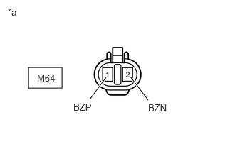
E360297C12
0.417,0.99 0.906,1.292 0.49,0.302 1.313,1.458 1.552,1.135 true 1.906,1.125 2.167,1.469 true 1.073,1.49 1.531,1.688 0.458,0.198 10 false BZP 2.167,1.5 2.625,1.698 0.458,0.198 10 false BZN 0.115,0.094 0.427,0.292 0.313,0.198 10 false *a 0.542,1.063 0.938,1.354 0.396,0.292 10 false M64
*a Front view of wire harness connector
(to RCTA Buzzer (Blind Spot Monitor Buzzer))


Disconnect the RCTA buzzer (blind spot monitor buzzer) connector.


b.

Measure the voltage according to the value(s) in the table below.

Standard Voltage:
Tester Connection Switch Condition Specified Condition
M64-1 (BZP) - Body ground Ignition switch ON 11 to 14 V
M64-2 (BZN) or M63-3 (BUZ) - Body ground Below 1 V
M64-2 (BZN) - M64-1 (BZP) Below 1 V


Result:
Proceed to
OK
NG


OK

3.CHECK HARNESS AND CONNECTOR (RCTA BUZZER (BLIND SPOT MONITOR BUZZER) - BLIND SPOT MONITOR SENSOR RH (A) AND BATTERY)

NG

REPAIR OR REPLACE HARNESS OR CONNECTOR

3.CHECK HARNESS AND CONNECTOR (RCTA BUZZER (BLIND SPOT MONITOR BUZZER) - BLIND SPOT MONITOR SENSOR RH (A) AND BATTERY)
a.
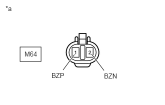
E360297C13
0.417,0.979 0.854,1.281 0.438,0.302 1.313,1.458 1.552,1.135 true 1.906,1.125 2.167,1.469 true 1.073,1.49 1.531,1.688 0.458,0.198 10 false BZP 2.167,1.5 2.625,1.698 0.458,0.198 10 false BZN 0.115,0.094 0.427,0.292 0.313,0.198 10 false *a 0.51,1.042 0.896,1.333 0.385,0.292 10 false M64
*a Front view of wire harness connector
(to RCTA Buzzer (Blind Spot Monitor Buzzer))


Disconnect the RCTA buzzer (blind spot monitor buzzer) connector.


b.

Disconnect the M63 blind spot monitor sensor RH (A) connector.


c.

Measure the resistance according to the value(s) in the table below.

Standard Resistance:
Tester Connection Condition Specified Condition
M64-2 (BZN) - M63-3 (BUZ) Always Below 1 Ω
M64-2 (BZN) or M63-3 (BUZ) - Body ground Always 10 kΩ or higher


d.

Measure the voltage according to the value(s) in the table below.

Standard Voltage:
Tester Connection Switch Condition Specified Condition
M64-2 (BZN) or M63-3 (BUZ) - Body ground Ignition switch ON Below 1 V
M64-1 (BZP) - Body ground Ignition switch ON 11 to 14 V
M64-1 (BZP) - Body ground Ignition switch off Below 1 V


Result:
Proceed to
OK
NG


OK

NG

REPAIR OR REPLACE HARNESS OR CONNECTOR