CRUISE CONTROL DYNAMIC RADAR CRUISE CONTROL SYSTEM Neutral Position Switch Circuit
DESCRIPTION
The neutral position switch detects whether the shift lever is in neutral. If the shift lever is moved to neutral for a certain period of time or more, control of vehicle speed by the dynamic radar cruise control system is canceled.
WIRING DIAGRAM
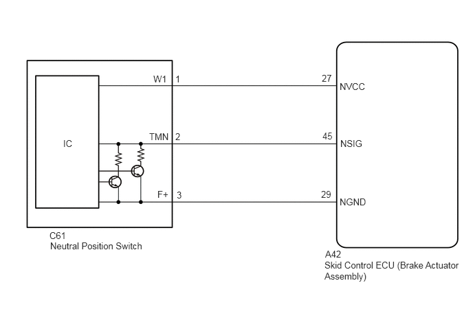
PROCEDURE
Disconnect the A42 Skid Control ECU (Brake Actuator Assembly) connector.
Disconnect the C61 neutral position switch connector.
Measure the resistance according to the value(s) in the table below.
- Standard Resistance:
Tester Connection Condition Specified Condition A42-27 (NVCC) - C61-1 (W1) Always Below 1 Ω A42-45 (NSIG) - C61-2 (TMN) Always Below 1 Ω A42-29 (NGND) - C61-3 (F+) Always Below 1 Ω A42-27 (NVCC) or C61-1 (W1) - Other terminals and body ground Always 10 kΩ or higher A42-45 (NSIG) or C61-2 (TMN) - Other terminals and body ground Always 10 kΩ or higher A42-29 (NGND) or C61-3 (F+) - Other terminals and body ground Always 10 kΩ or higher
Connect the C61 neutral position switch connector.
Connect the A42 Skid Control ECU (Brake Actuator Assembly) connector.
- Result:
Proceed to OK NG
OK
NG
Disconnect the neutral position switch connector.
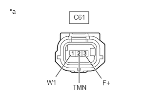
| *a | Front view of wire harness connector
(to Neutral Position Switch) |
Measure the voltage according to the value(s) in the table below.
- Standard Voltage:
Tester Connection Switch Condition Specified Condition C61-1 (W1) - Body ground Ignition switch ON 4.5 to 5.5 V
Measure the resistance according to the value(s) in the table below.
- Standard Resistance:
Tester Connection Condition Specified Condition C61-1 (W1) - C61-2 (TMN) Always 995 to 1005 Ω C61-3 (F+) - Body ground Always Below 1 Ω
Connect the neutral position switch connector.
- Result:
Result Proceed to OK A NG (for LHD) B NG (for RHD) C
A
B
C