RM32H0E
_57
Power Source / Network
_060209
8NR-FTS BATTERY / CHARGING
_0295688
CHARGING SYSTEM
C
8NR-FTS BATTERY / CHARGING CHARGING SYSTEM P16027B Deterioration of Battery Low Fluid Level
DESCRIPTION
The ECM determines the battery status according to the voltage of the BATT terminal while the engine is running (not cranking).
| DTC No. | Detection Item | DTC Detection Condition | Trouble Area | Warning Indicate | Memory | Note |
|---|---|---|---|---|---|---|
| P16027B | Deterioration of Battery Low Fluid Level | Battery capacity is low for 10 seconds or more when the engine is running (not cranking).
(1 trip detection logic) |
·
Battery ·
Wire harness or connector |
Charge warning light does not come on | DTC stored | SAE Code: P1602 |
WIRING DIAGRAM
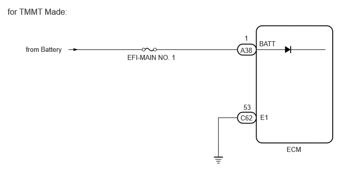
0.531,0.927 2.365,1.125
1.833,0.198
10
false
from Battery
5.323,0.813 5.938,1.01
0.615,0.198
10
false
BATT
5.344,2.323 5.656,2.521
0.313,0.198
10
false
E1
4.938,0.948 5.396,1.146
0.458,0.198
10
false
A38
5.021,0.698 5.177,0.896
0.156,0.198
10
false
1
4.938,2.333 5.396,2.531
0.458,0.198
10
false
C62
5,2.115 5.313,2.313
0.313,0.198
10
false
53
5.885,2.979 6.344,3.177
0.458,0.198
10
false
ECM
2.615,1.094 4.76,1.292
2.146,0.198
10
false
EFI-MAIN NO. 1
0.156,0.135 1.698,0.448
1.542,0.313
12
false
for TMMT Made:
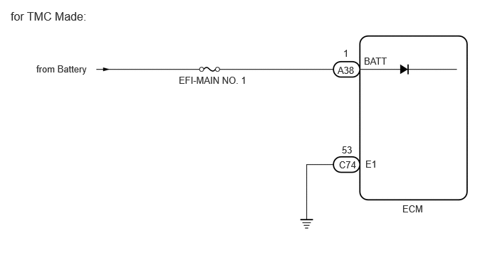
0.531,0.927 2.365,1.125
1.833,0.198
10
false
from Battery
5.323,0.813 5.938,1.01
0.615,0.198
10
false
BATT
5.344,2.323 5.656,2.521
0.313,0.198
10
false
E1
4.938,0.948 5.396,1.146
0.458,0.198
10
false
A38
5.021,0.698 5.177,0.896
0.156,0.198
10
false
1
4.958,2.333 5.417,2.531
0.458,0.198
10
false
C74
5,2.115 5.313,2.313
0.313,0.198
10
false
53
5.885,2.979 6.344,3.177
0.458,0.198
10
false
ECM
2.615,1.094 4.76,1.292
2.146,0.198
10
false
EFI-MAIN NO. 1
0.156,0.135 1.49,0.396
1.333,0.26
12
false
for TMC Made:
CAUTION / NOTICE / HINT
- NOTICE:
-
Inspect the fuses for circuits related to this system before performing the following procedure.
- HINT:
-
If any DTCs other than P16027B are output, troubleshoot those DTCs first.
PROCEDURE
1.CHECK CHARGING SYSTEM
a.
Check the charging system.
Click herePower Source / Network>8NR-FTS (BATTERY / CHARGING)>CHARGING SYSTEM>ON-VEHICLE INSPECTION
- Result:
Result OK NG
OK
2.CHECK HARNESS AND CONNECTOR (POWER SOURCE CIRCUIT)
NG
REPAIR OR REPLACE CHARGING SYSTEM
2.CHECK HARNESS AND CONNECTOR (POWER SOURCE CIRCUIT)
a.
Disconnect the ECM connector.
b.
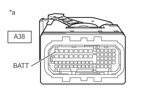
0.167,0.667 0.667,0.917
0.5,0.25
0.667,1.417 1.198,1.104
true
0.198,0.177 0.51,0.375
0.313,0.198
10
false
*a
0.281,1.323 0.708,1.552
0.427,0.229
10
false
BATT
0.292,0.698 0.906,0.896
0.615,0.198
10
false
A38
| *a | Front view of wire harness connector
(to ECM) |
Measure the voltage according to the value(s) in the table below.
- Standard Voltage:
Tester Connection Condition Specified Condition A38-1 (BATT) - Body ground Always 11 to 14 V
- Result:
Result OK NG
OK
CHECK FOR INTERMITTENT PROBLEMS
Click hereGeneral>INTRODUCTION>HOW TO TROUBLESHOOT ECU CONTROLLED SYSTEMS>HOW TO PROCEED WITH TROUBLESHOOTING
NG
REPAIR OR REPLACE HARNESS OR CONNECTOR