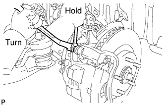
Install the disc brake cylinder assembly with the 2 bolts.
Torque:
34 N*m{
350 kgf*cm
, 25 ft.*lbf
}
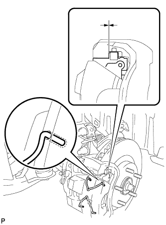
Check the installation of the anti-squeal springs.
Visually check for any clearance between the brake pad and front disc brake pad support plates as shown in the illustration.
NOTICE:
If the anti-squeal springs are installed correctly, there will be no clearance between the brake pad and the front disc brake pad support plates. If there is a clearance, the anti-squeal springs may not be installed properly.
Check all 4 contact surfaces between the brake pad and the front disc brake pad support plates.
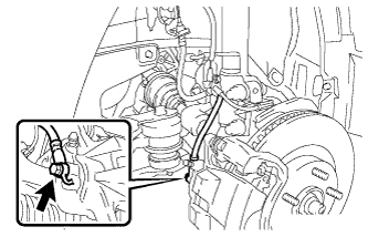
Connect the front brake flexible hose with the union bolt and a new gasket.
Torque:
29 N*m{
300 kgf*cm
, 21 ft.*lbf
}
NOTICE:
Install the front brake flexible hose lock securely in the lock hole in the disc brake cylinder assembly.
2.
FILL RESERVOIR WITH BRAKE FLUID
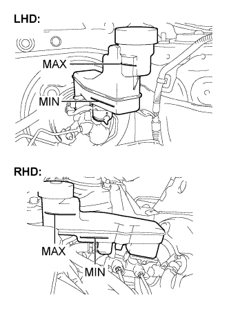
Fill the reservoir with brake fluid.
Fluid:
SAE J1703 or FMVSS No. 116 DOT3
3.
BLEED MASTER CYLINDER
HINT:
If the master cylinder is reinstalled or if the reservoir becomes empty, bleed the air from the master cylinder.
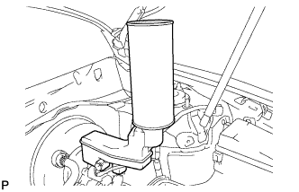
To avoid brake fluid from contacting and/or damaging, cover the painted surface with a shop rag or a piece of cloth.
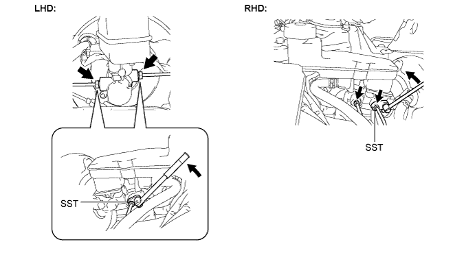
Using SST, disconnect the 2 brake lines from the master cylinder.
SST
09023-00101
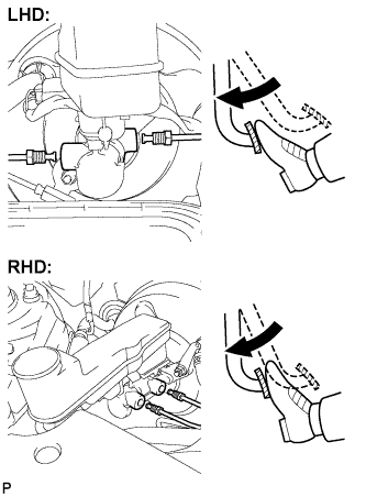
Slowly depress the brake pedal and hold it (*1).
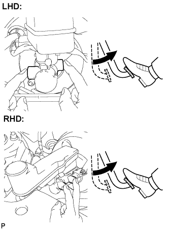
Cover the 2 outer holes with fingers, and release the brake pedal (*2).
Repeat (*1) and (*2) 3 or 4 times.
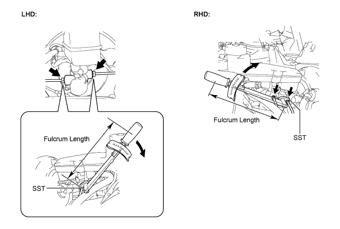
Using SST, connect the 2 brake lines to the master cylinder.
SST
09023-00101
Torque:
Without SST for RHD with VSC:
19 N*m{
194 kgf*cm
, 17 ft.*lbf
}
With SST for RHD with VSC:
17 N*m{
174 kgf*cm
, 13 ft.*lbf
}
Without SST except RHD with VSC:
15 N*m{
155 kgf*cm
, 11 ft.*lbf
}
With SST except RHD with VSC:
14 N*m{
143 kgf*cm
, 10 ft.*lbf
}
NOTICE:
Use a torque wrench with a fulcrum length of 250 mm (9.84 in.).
This torque value is effective when SST is parallel to a torque wrench.
4.
BLEED BRAKE LINE
NOTICE:
Bleed the air from the brake line of the wheel farthest from the master cylinder.
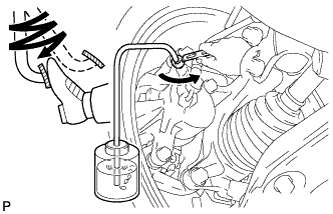
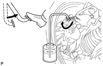
Connect a vinyl tube to the bleeder plug.
Depress the brake pedal several times, then loosen the bleeder plug with the pedal depressed (*3).
When fluid stops coming out, tighten the bleeder plug, then release the brake pedal (*4).
Repeat (*3) and (*4) until all the air in the fluid is completely bled out.
Tighten the bleeder plug completely.
Torque:
for LHD:
8.3 N*m{
85 kgf*cm
, 73 in.*lbf
}
for RHD:
12 N*m{
122 kgf*cm
, 9 ft.*lbf
}
Repeat the above procedures for each wheel to bleed the air from the brake line.
5.
INSPECT BRAKE FLUID LEVEL IN RESERVOIR
Check the fluid level. If brake fluid level is low, check for leakage and inspect the disc brake pad. If necessary, refill the reservoir with brake fluid after repair and replacement.