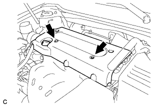
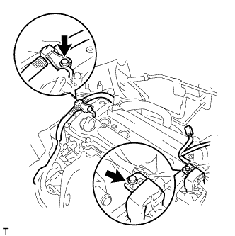
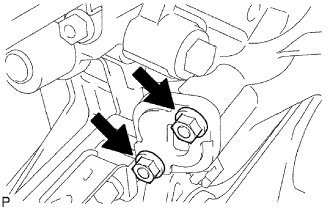
Remove the 2 bolts and disconnect the 2 engine wires.
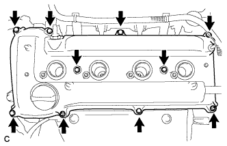
Remove the 8 bolts, 2 nuts, and the cylinder head cover.
10.
SET NO. 1 CYLINDER TO TDC/COMPRESSION
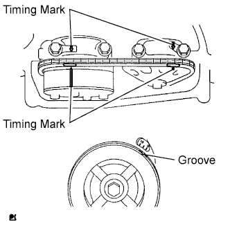
Turn the crankshaft pulley until its groove and the timing mark "0" of the timing chain cover are aligned.
Check that each timing mark of the camshaft timing gear and sprocket is aligned with each timing mark located on the No. 1 and No. 2 bearing caps as shown in the illustration. If not, turn the crankshaft 1 revolution (360°) to align the timing marks as above.
11.
REMOVE NO. 1 CHAIN TENSIONER ASSEMBLY
Remove the 2 nuts, tensioner and gasket.
NOTICE:
Do not turn the crankshaft without the chain tensioner.
12.
REMOVE NO. 2 CAMSHAFT
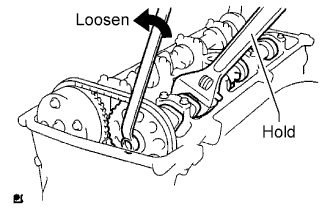
While holding the camshaft with a wrench, loosen the camshaft timing set bolt.
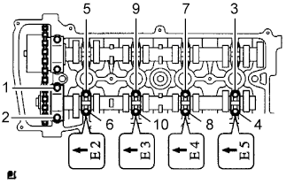
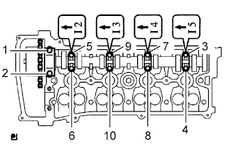
Using several steps, uniformly loosen and remove the 10 bearing cap bolts in the sequence shown in the illustration.
Remove the 5 bearing caps.
While holding the No. 2 camshaft by hand, remove the camshaft timing sprocket set bolt.
Remove the camshaft timing sprocket from the No. 2 camshaft with the timing chain on the sprocket.
Remove the camshaft timing sprocket from the timing chain.
13.
REMOVE CAMSHAFT
Using several steps, uniformly loosen and remove the 10 bearing cap bolts in the sequence shown in the illustration.
Remove the 5 bearing caps.
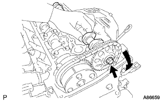
Remove the camshaft and camshaft timing gear while holding the timing chain by hand.
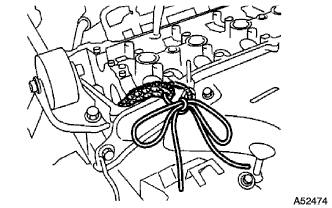
Tie the timing chain with a string as shown in the illustration.
NOTICE:
Be careful not to drop anything inside the timing chain cover.
14.
REMOVE CAMSHAFT TIMING GEAR ASSEMBLY
Clamp the camshaft in a vise, and make sure that the camshaft timing gear does not rotate.
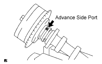
Cover all the oil ports except the advance side port shown in the illustration with vinyl tape.
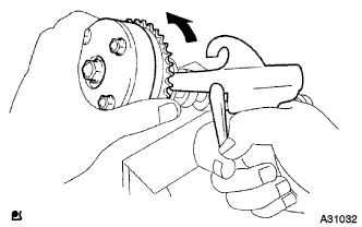
Apply air pressure of 100 kPa (1.0 kgf/cm2, 14 psi) to the oil path, then turn the camshaft timing gear in the advance direction (counterclockwise) by hand.
CAUTION:
Cover the paths with a shop rag or piece of cloth to keep oil from splashing.
HINT:
Depending on the air pressure, the camshaft timing gear will turn to the advance angle side without applying force by hand. Also, if the pressure is difficult to apply because of air leakage from the port, the lock may be difficult to release.
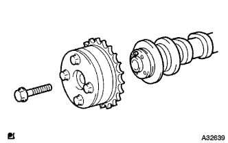
Remove the flange bolt of the camshaft timing gear.
NOTICE:
Be sure not to remove the other 4 bolts.
If the gear is to be reused, be sure to release the straight pin lock before installing the gear.