REASSEMBLY
Removal / installation · Vehicles built from Jun 2009
Versions by build date: Jun 2006 – Sep 2006 Oct 2006 – May 2009 from Jun 2009
| 1.
INSTALL CLUTCH DISC ASSEMBLY |
 |
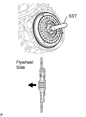
- Insert SST into the clutch disc assembly, then insert them into the flywheel sub-assembly.
- SST
- 09301-00220
- NOTICE:
- Take care not to insert the clutch disc assembly in the wrong direction.
| 2.
INSTALL CLUTCH COVER ASSEMBLY |
|
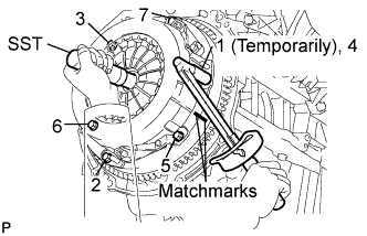
- Align the matchmarks on the clutch cover assembly with the one on the flywheel sub-assembly.
Following the procedures shown in the illustration, tighten the 6 bolts in order, starting with the bolt located near the knock pin on the top.
-
Torque:
- 19 N*m{
195 kgf*cm
, 14 ft.*lbf
}
- HINT:
- Following the order in the illustration, evenly tighten the bolts one turn at a time.
- Lightly move SST up and down, and right and left after checking that the disc is in the center to tighten the bolts.
- SST
- 09301-00210
| 3.
INSTALL RELEASE FORK SUPPORT |
|
- Install the release fork support to the manual transaxle assembly.
-
Torque:
- 47 N*m{
480 kgf*cm
, 35 ft.*lbf
}
| 4.
INSTALL RELEASE BEARING HUB CLIP |
|
Install the release bearing hub clip to the release bearing assembly.
| 5.
INSTALL CLUTCH RELEASE FORK SUB-ASSEMBLY |
|
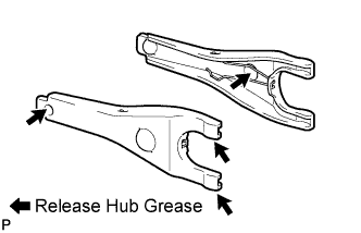
- Apply release hub grease to the contact surfaces between the release fork and release bearing, fork and push rod, and fork and fork support.
- Sealant:
- Part No. 08887-01806, RELEASE HUB GREASE or equivalent
Install the release fork to the release bearing assembly.
| 6.
INSTALL CLUTCH RELEASE BEARING ASSEMBLY |
|
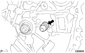
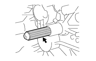
- Apply clutch spline grease to the input shaft spline as shown in the illustration.
- Sealant:
- Part No. 08887-01706, CLUTCH SPLINE GREASE or equivalent
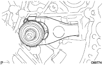
- Install the release fork with the release bearing assembly to the manual transaxle assembly.
- NOTICE:
- After installation, move the fork back and forth to check that the release bearing slides smoothly.
| 7.
INSTALL CLUTCH RELEASE FORK BOOT |
|
| 8.
INSTALL MANUAL TRANSAXLE ASSEMBLY |
|
Click here.