Fuel Injector Circuit
Circuit diagnosis · Vehicles built Jun 2006 – May 2009
Versions by build date: Jun 2006 – May 2009 from Jun 2009
DESCRIPTION
The fuel injectors are located on the intake manifold. They inject fuel into the cylinders based on the signals from the ECM.WIRING DIAGRAM
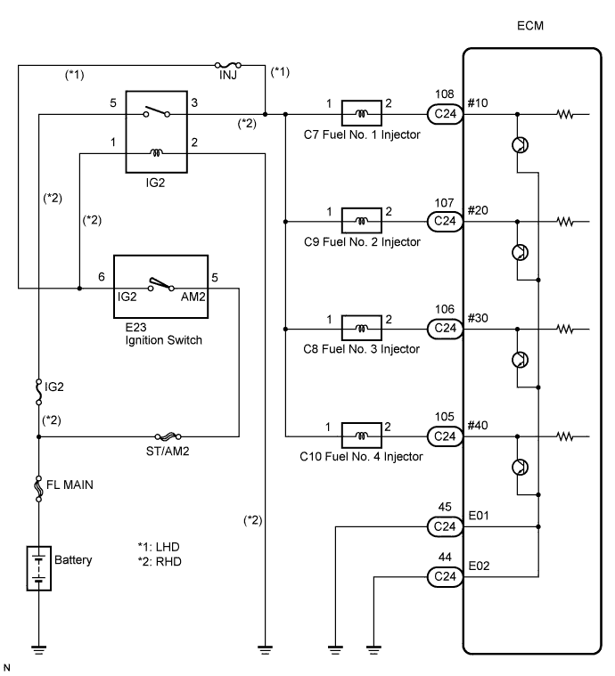

INSPECTION PROCEDURE
| 1. INSPECT ECM (#10, #20, #30, #40 VOLTAGE) |

Disconnect the C24 ECM connector.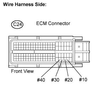
Turn the ignition switch to the ON position.
Measure the voltage according to the value(s) in the table below.
- Standard voltage:
Tester Connection
Specified Condition
#10 (C24-108) - Body ground
9 to 14 V
#20 (C24-107) - Body ground
#30 (C24-106) - Body ground
#40 (C24-105) - Body ground
Reconnect the ECM connector.
|
|
||||

| NG | |
 |
| 2. INSPECT FUEL INJECTOR (RESISTANCE) |
Inspect the fuel injector (Click here).
|
|
||||

| OK | |
|
| 3. CHECK HARNESS AND CONNECTOR |
Disconnect the C7 to C10 injector connectors.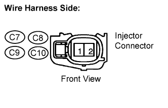
Turn the ignition switch to the ON position.
Measure the voltage according to the value(s) in the table below.
- Standard voltage:
Cylinder
Tester Connection
Specified Condition
No. 1
C7-1 - Body ground
11 to 14 V
No. 2
C9-1 - Body ground
No. 3
C8-1 - Body ground
No. 4
C10-1 - Body ground
- Result:
Result
Proceed to
NG (RHD)
A
NG (LHD)
B
OK
C
Reconnect the injector connectors.
|
|
||||
|
|
||||
| A | |
|
| 4. INSPECT IGNITION RELAY NO. 2 |
Remove the IG2 relay from the engine room R/B.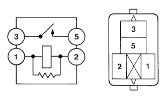
Measure the resistance between the terminals.
- Standard resistance:
Tester Connection
Specified Condition
3 - 5
10 kΩ or higher
Below 1 Ω
(Apply battery voltage between terminals 1 and 2)
Reinstall the IG2 relay.
|
|
||||
| OK | |
|
| 5. CHECK HARNESS AND CONNECTOR (IG2 RELAY - BODY GROUND) |
Remove the IG2 relay from the engine room R/B.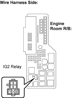
Measure the resistance according to the value(s) in the table below.
- Standard resistance:
Tester Connection
Specified Condition
IG2 relay terminal 2 - Body ground
Below 1 Ω
Reinstall the IG2 relay.
|
|
||||
| NG | ||
 |
||
| ||
| 6. INSPECT FUSE (INJ FUSE) |
Remove the INJ fuse from the instrument panel J/B.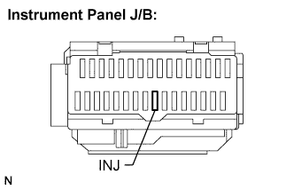
Measure the fuse resistance.
- Standard resistance:
- Below 1 Ω
Reinstall the fuse.
|
|
||||
| OK | |
|
| 7. INSPECT IGNITION SWITCH |
Disconnect the E23 ignition switch connector.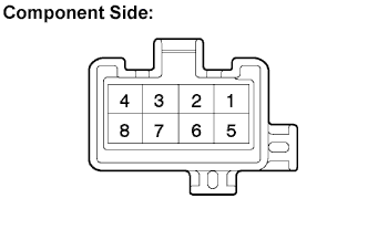
Measure the resistance according to the value(s) in the table below.
- Standard resistance:
Tester Connection
Ignition Switch Position
Specified Condition
All Terminals
LOCK
10 kΩ or higher
2 - 4
ACC
Below 1 Ω
1 - 2 - 4, 5 - 6
ON
1 - 3 - 4, 5 - 6 - 7
START
Reconnect the ignition switch connector.
|
|
||||
| OK | ||
|
||
| ||
| 8. CHECK HARNESS AND CONNECTOR (INJECTOR - ECM) |
Disconnect the C7 to C10 injector connectors.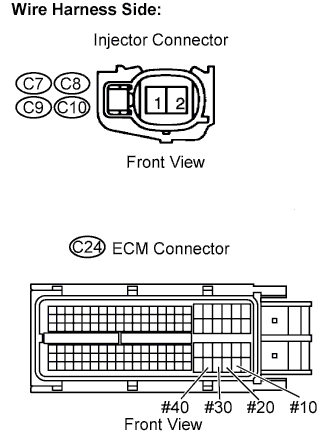
Disconnect the C24 ECM connector.
Measure the resistance according to the value(s) in the table below.
- Standard resistance:
Cylinder
Tester Connection
Specified Condition
No. 1
C7-2 or #10 (C24-108) - Body ground
10 kΩ or higher
C7-2 - #10 (C24-108)
Below 1 Ω
No. 2
C9-2 or #20 (C24-107) - Body ground
10 kΩ or higher
C9-2 - #20 (C24-107)
Below 1 Ω
No. 3
C8-2 or #30 (C24-106) - Body ground
10 kΩ or higher
C8-2 - #30 (C24-106)
Below 1 Ω
No. 4
C10-2 or #40 (C24-105) - Body ground
10 kΩ or higher
C10-2 - #40 (C24-105)
Below 1 Ω
Reconnect the injector connectors.
Reconnect the ECM connector.
|
|
||||
| OK | |
|
| 9. CHECK HARNESS AND CONNECTOR (ECM - BODY GROUND) |
Disconnect the C24 ECM connector.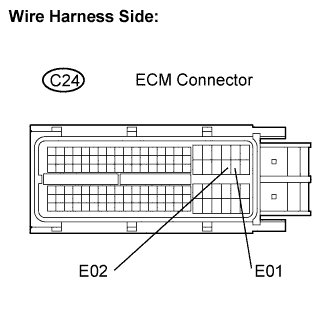
Measure the resistance according to the value(s) in the table below.
- Standard resistance:
Tester Connection
Specified Condition
E01 (C24-45) - Body ground
Below 1 Ω
E02 (C24-44) - Body ground
Below 1 Ω
Reconnect the ECM connector.
|
|
||||
| OK | |
|
| 10. INSPECT FUEL INJECTOR (FUEL INJECTION VOLUME) |
Inspect the fuel injector (Click here).
|
|
||||
| OK | ||
|
||
| ||