TERMINALS OF ECU
System information · Vehicles built from Jun 2009
Versions by build date: Oct 2006 – May 2009 from Jun 2009
| CHECK OUTER MIRROR CONTROL ECU |
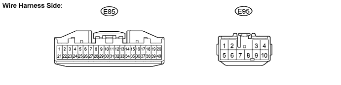

Disconnect the E85 and E95 connectors.
Measure the voltage and resistance according to the value(s) in the table below.
- Standard voltage:
Symbols (Terminal No.)
Wiring Color
Terminal Description
Condition
Specified Condition
ACC (E95-4) - Body ground
B-R - Body ground
Ignition power supply
Engine switch off → on (ACC)
0 V → 10 to 14 V
B (E95-3) - Body ground
W-R - Body ground
+B power supply
Always
10 to 14 V
- Standard resistance:
Symbols (Terminal No.)
Wiring Color
Terminal Description
Condition
Specified Condition
GND (E95-9) - Body ground
W-B - Body ground
Ground
Always
Below 1 Ω
Reconnect the E85 and E95 connectors.
Measure the voltage according to the value(s) in the table below.
- Standard voltage:
Symbols (Terminal No.)
Wiring Color
Terminal Description
Condition
Specified Condition
+CB (E85-2) - Body ground
GR - Body ground
Power source for mirror position sensor
Engine switch off → on (ACC)
0 V → 0 to 5 V
VSR (E85-4) - Body ground
G - Body ground
Vertical direction position signal
Engine switch on (ACC), Left/Right adjustment switch L side, Mirror switch uppermost position → lowermost position
3.7 V → 1.3 V
HSRL (E85-5) - Body ground
L - Body ground
Horizontal direction position signal
Engine switch on (ACC), Left/Right adjustment switch L side, Mirror switch innermost position → outermost position
3.7 V → 1.3 V
M+L (E85-18) - Body ground
BE - Body ground
Outer mirror switch signal (Right or Down)
Engine switch on (ACC), Left/Right adjustment switch L side, Mirror switch OFF → RIGHT or DOWN
0 V → 10 to 14 V
MHL (E85-19) - Body ground
P - Body ground
Outer mirror switch signal (Left or Down)
Engine switch on (ACC), Left/Right adjustment switch L side, Mirror switch OFF → LEFT or DOWN
0 V → 10 to 14 V
MVL (E85-20) - Body ground
LG - Body ground
Outer mirror switch signal (Up or Right)
Engine switch on (ACC), Left/Right adjustment switch L side, Mirror switch OFF → UP or Right
0 V → 10 to 14 V
VSRR (E85-24) - Body ground
G - Body ground
Vertical direction position signal
Engine switch on (ACC), Left/Right adjustment switch R side, Mirror switch uppermost position → lowermost position
3.7 V → 1.3 V
HSRR (E85-25) - Body ground
L - Body ground
Horizontal direction position signal
Engine switch on (ACC), Left/Right adjustment switch R side, Mirror switch innermost position → outermost position
1.3 V → 3.7 V
M+R (E85-38) - Body ground
BE - Body ground
Outer mirror switch signal (Right or Down)
Engine switch on (ACC), Left/Right adjustment switch R side, Mirror switch OFF → RIGHT or DOWN
0 V → 10 to 14 V
MHR (E85-39) - Body ground
LG - Body ground
Outer mirror switch signal (Left or Down)
Engine switch on (ACC), Left/Right adjustment switch R side, Mirror switch OFF → LEFT or DOWN
0 V → 10 to 14 V
MVR (E85-40) - Body ground
P - Body ground
Outer mirror switch signal (Up or Right)
Engine switch on (ACC), Left/Right adjustment switch R side, Mirror switch OFF → UP or Right
0 V → 10 to 14 V