INSTALLATION
Removal / installation · Vehicles built Jun 2006 – Sep 2006
Versions by build date: Jun 2006 – Sep 2006 Oct 2006 – May 2009 from Jun 2009
| 1.
INSTALL CLUTCH MASTER CYLINDER PUSH ROD CLEVIS BUSHING |
 |
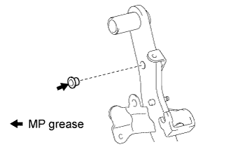
- Apply MP grease to the inside of a new clevis bushing.
Install the clevis bushing to the clutch pedal.
- HINT:
- Install the clevis bushing from the left side of the vehicle.
| 2.
INSTALL CLUTCH PEDAL TURNOVER BUSHING (for LHD) |
|
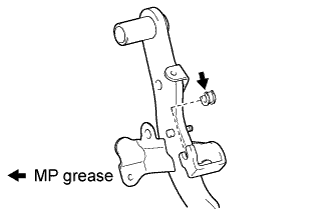
- Apply MP grease to the inside of the turnover bushing.
Install the turnover bushing to the clutch pedal.
| 3.
INSTALL CLUTCH PEDAL TURNOVER BUSHING (for RHD) |
|
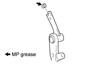
- Apply MP grease to the inside of the turnover bushing.
Install the turnover bushing to the clutch pedal.
| 4.
INSTALL NO. 1 CLUTCH PEDAL CUSHION (for LHD) |
|
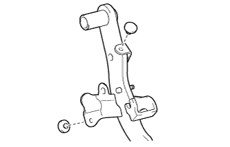
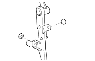
- Using needle-nose pliers, install the 2 No. 1 clutch pedal cushions to the clutch pedal.
| 5.
INSTALL NO. 1 CLUTCH PEDAL CUSHION (for RHD) |
|
- Using needle-nose pliers, install the 2 No. 1 clutch pedal cushions to the clutch pedal.
| 6.
INSTALL CLUTCH PEDAL BUSHING |
|
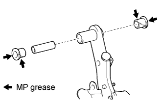
- Apply MP grease to the inner, outer and end surfaces of 2 new pedal bushings.
Install the clutch pedal shaft collar and 2 pedal bushings to the clutch pedal.
| 7.
INSTALL CLUTCH PEDAL PAD |
|
Install the clutch pedal pad to the clutch pedal.
| 8.
INSTALL CLUTCH PEDAL SPRING HOLDER |
|
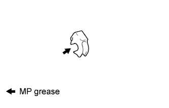
- Apply MP grease to the inside of a new clutch pedal spring holder.
Install the clutch pedal spring holder.
| 9.
INSTALL CLUTCH PEDAL SUB-ASSEMBLY |
|
- Install the clutch pedal to the clutch pedal support with the bolt and nut.
-
Torque:
- 37 N*m{
375 kgf*cm
, 27 ft.*lbf
}
- HINT:
- Install the bolt from the right side of the vehicle.
| 10.
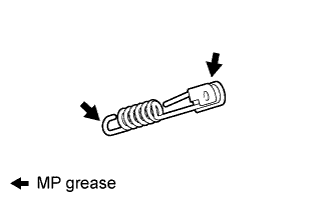
INSTALL PEDAL WITH HOOK SPRING |
|
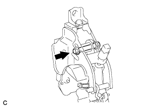
- Apply MP grease to the sliding portion of the spring.
Install the hook spring.
| 11.
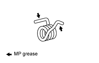
INSTALL TORSION SPRING |
|
- Apply MP grease to the sliding portion of the spring.
Install the torsion spring.
| 12.
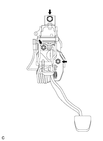
INSTALL CLUTCH PEDAL SUPPORT SUB-ASSEMBLY (for LHD) |
|
- Install the clutch pedal support to the vehicle with the 2 nuts and bolt.
-
Torque:
- Bolt:
- 19 N*m{
195 kgf*cm
, 14 ft.*lbf
}
- Nut:
- 12 N*m{
120 kgf*cm
, 9 ft.*lbf
}
| 13.
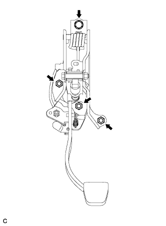
INSTALL CLUTCH PEDAL SUPPORT SUB-ASSEMBLY (for RHD) |
|
- Install the clutch pedal support to the vehicle with the 3 nuts and bolt.
-
Torque:
- Bolt:
- 19 N*m{
195 kgf*cm
, 14 ft.*lbf
}
- Nut:
- 12 N*m{
120 kgf*cm
, 9 ft.*lbf
}
| 14.
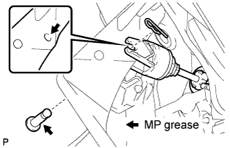
INSTALL CLUTCH MASTER CYLINDER PUSH ROD CLEVIS PIN |
|
- Apply MP grease to the contact surface of the pin and clevis bushing.
Connect the clevis pin to the clutch pedal with the pin and a new clip.
- HINT:
- Install the pin from the left side of the vehicle.
| 15.
CONNECT CONNECTORS |
|
Connect the clutch start switch connector.
Connect the clutch switch connector (with cruise control).
| 16.
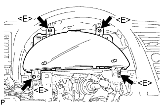
INSTALL COMBINATION METER ASSEMBLY
|
|
- Connect each connector.
Install the combination meter assembly with the 4 screws <E>.
| 17.
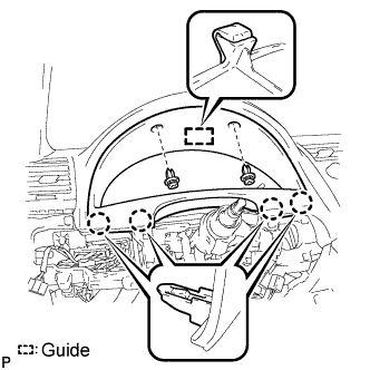
INSTALL INSTRUMENT CLUSTER FINISH PANEL SUB-ASSEMBLY
|
|
- Engage the guide and the 4 claws.
Install the instrument cluster finish panel sub-assembly with the 2 clips.
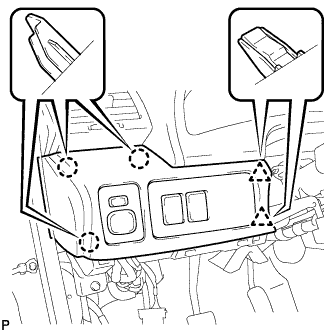
| 18.
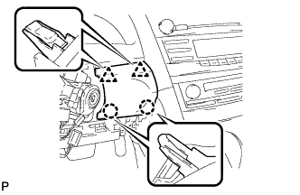
INSTALL LOWER INSTRUMENT PANEL FINISH PANEL
|
|
- Engage the 2 claws and 2 clips to install the lower instrument panel finish panel.
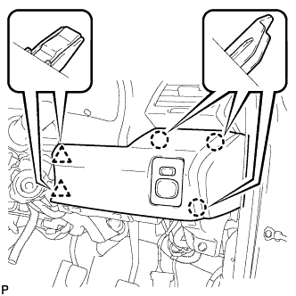
| 19.
INSTALL NO. 1 INSTRUMENT PANEL SUB-ASSEMBLY (for LHD)
|
|
Connect each connector.
- Engage the 3 claws and 2 clips to install the No. 1 instrument panel sub-assembly.
| 20.
INSTALL NO. 1 INSTRUMENT PANEL SUB-ASSEMBLY (for RHD)
|
|
Connect each connector.
- Engage the 3 claws and 2 clips to install the No. 1 instrument panel sub-assembly.
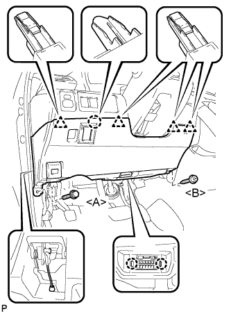
| 21.
INSTALL LOWER NO. 1 INSTRUMENT PANEL FINISH PANEL LH
|
|
- Install the air hose and connect the connector.
Engage the 2 claws and the DLC3.
Engage the claw and the 4 clips.
Install the lower No. 1 instrument panel finish panel with the screw <B> and bolt <A>.
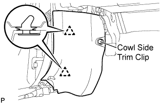
| 22.
INSTALL COWL SIDE TRIM SUB-ASSEMBLY LH
|
|
- Engage the 2 clips.
Install the cowl side trim sub-assembly LH with the cowl side trim clip.
| 23.
INSTALL FRONT DOOR SCUFF PLATE LH
|
|
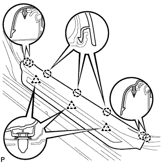
- Engage the 7 claws and 3 clips, then install the front door scuff plate LH.
| 24.
CONNECT CABLE TO NEGATIVE BATTERY TERMINAL |
|
| 25.
INSPECT AND ADJUST CLUTCH PEDAL SUB-ASSEMBLY |
|
Click here.