INSTALLATION
Removal / installation · Vehicles built from Jun 2009
Versions by build date: Oct 2006 – May 2009 from Jun 2009
| 1. INSTALL VANE PUMP ASSEMBLY |

Temporarily install the bolt to the vane pump assembly.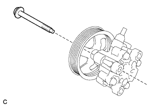

Install the vane pump assembly.
Temporarily install bolt (B).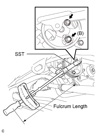
Using SST, tighten the 2 bolts.
- SST
- 09249-63010
- Torque:
- Without SST:
- 43 N*m{ 439 kgf*cm , 32 ft.*lbf }
- With SST:
- 29 N*m{ 294 kgf*cm , 21 ft.*lbf }
- NOTICE:
- Use a torque wrench with a fulcrum length of 300 mm (11.81 in.).
- This torque value is accurate when SST is parallel to the torque wrench.
- Use a torque wrench with a fulcrum length of 300 mm (11.81 in.).
| 2. CONNECT POWER STEERING FLUID PRESSURE SWITCH CONNECTOR |
Connect the connector to the power steering fluid pressure switch.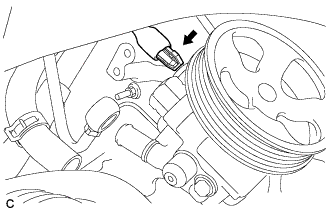
| 3. CONNECT PRESSURE FEED TUBE ASSEMBLY (for LHD) |
Install a new gasket to the pressure feed tube assembly.
Temporarily connect the pressure feed tube assembly to the vane pump assembly with the union bolt.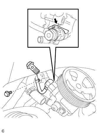
Install the pressure feed tube assembly clamp with the bolt.
- Torque:
- 9.8 N*m{ 100 kgf*cm , 87 in.*lbf }
- NOTICE:
- Install the pressure feed tube assembly clamp in the correct position.
Fully tighten the union bolt.
- Torque:
- 50 N*m{ 510 kgf*cm , 37 ft.*lbf }
- NOTICE:
- Make sure that the stopper of the pressure feed tube assembly contacts the vane pump assembly securely as shown in the illustration.
| 4. CONNECT PRESSURE FEED TUBE ASSEMBLY (for RHD) |
Install a new gasket to the pressure feed tube assembly.
Connect the pressure feed tube assembly to the vane pump assembly with the union bolt.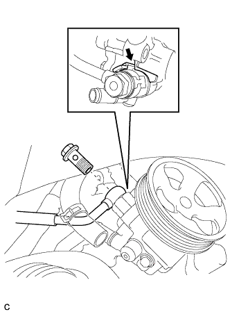
- Torque:
- 50 N*m{ 510 kgf*cm , 37 ft.*lbf }
- NOTICE:
- Make sure that the stopper of the pressure feed tube assembly contacts the vane pump assembly securely as shown in the illustration.
| 5. CONNECT NO. 1 FLUID RESERVOIR TO PUMP HOSE |
Connect the No. 1 fluid reservoir to pump hose to the vane pump assembly with the clip.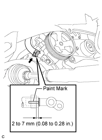
- NOTICE:
- Connect the No. 1 fluid reservoir to pump hose with the paint mark facing toward the rear of the vehicle.
- Push the No. 1 fluid reservoir to pump hose as far as it will go as shown in the illustration.
- Install the clip at the position specified in the illustration.
- Connect the No. 1 fluid reservoir to pump hose with the paint mark facing toward the rear of the vehicle.
| 6. INSTALL V-RIBBED BELT |
- HINT:
- Refer to the instructions for installation of the drive belt (Click here).
| 7. ADD POWER STEERING FLUID |
| 8. BLEED POWER STEERING FLUID |
Check the fluid level (Click here).
Jack up the front of the vehicle and support it with stands.
Turn the steering wheel.
With the engine stopped, turn the steering wheel slowly from lock to lock several times.
Lower the vehicle.
Start the engine.
Run the engine at idle for a few minutes.
Turn the steering wheel.
With the engine idling, turn the steering wheel to the left or right to the full lock position and keep it in that position for 2 to 3 seconds, then turn the steering wheel to the opposite full lock position and keep it there for 2 to 3 seconds.
Repeat this procedure several times.
Stop the engine.
Check for foaming or emulsification.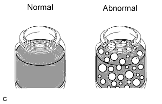
- HINT:
- If the system has to be bled twice because of forming or emulsification, be sure to check for fluid leaks in the system.
Check the fluid level (Click here).
| 9. CHECK POWER STEERING FLUID LEVEL |
Keep the vehicle level.
With the engine stopped, check the fluid level in the fluid reservoir.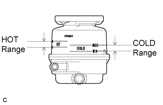
If necessary, add fluid.- Fluid:
- ATF DEXRON II or III, or equivalent
- HINT:
- If the fluid is hot, check that the fluid level is within the HOT range on the fluid reservoir. If the fluid is cold, check that the fluid level is within the COLD range.
Start the engine and run it at idle.
Turn the steering wheel from lock to lock several times to raise fluid temperature.
- Fluid temperature:
- 75°C (167°F) to 80°C (176°F)
Check for foaming or emulsification.
If foaming or emulsification is identified, bleed the power steering system (Click here).
With the engine idling, measure the fluid level in the fluid reservoir.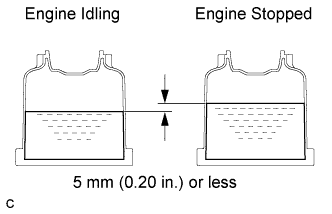
Stop the engine.
Wait a few minutes and remeasure the fluid level in the fluid reservoir.
- Maximum fluid level rise:
- 5 mm (0.20 in.)
Check the fluid level.
| 10. INSPECT FOR POWER STEERING FLUID LEAK |