Home › BODY › INTERIOR › ROOF HEADLININGINSTALLATION
Removal / installation · Vehicles built Oct 2006 – May 2009
Versions by build date: Jun 2006 – Sep 2006 Oct 2006 – May 2009 from Jun 2009
1.
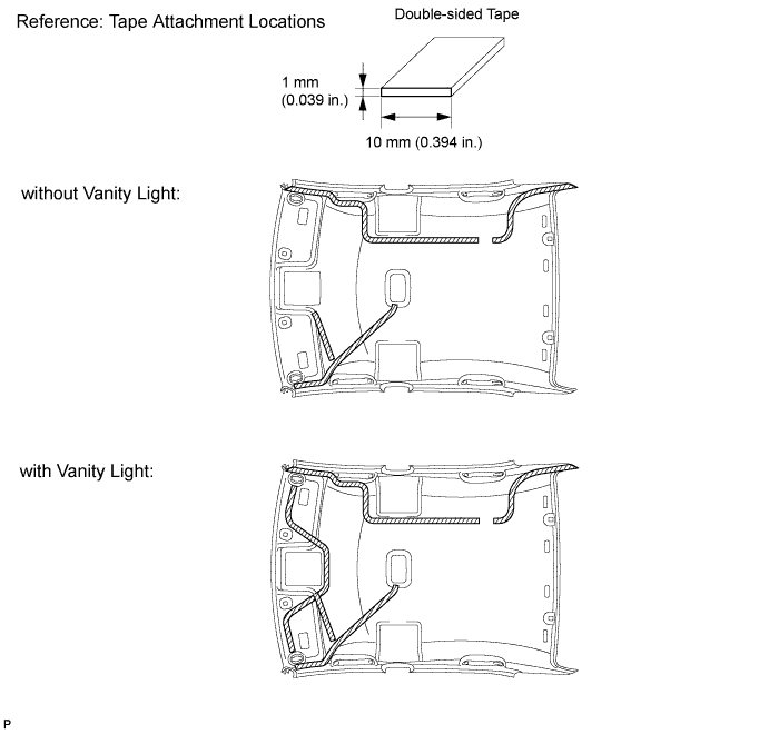
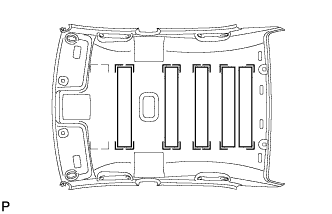
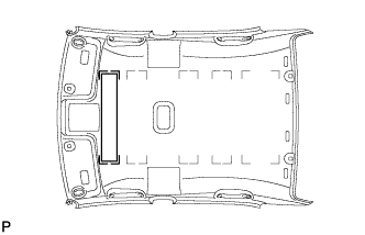
INSTALL NO. 1 ROOF WIRE (w/o Sliding Roof)
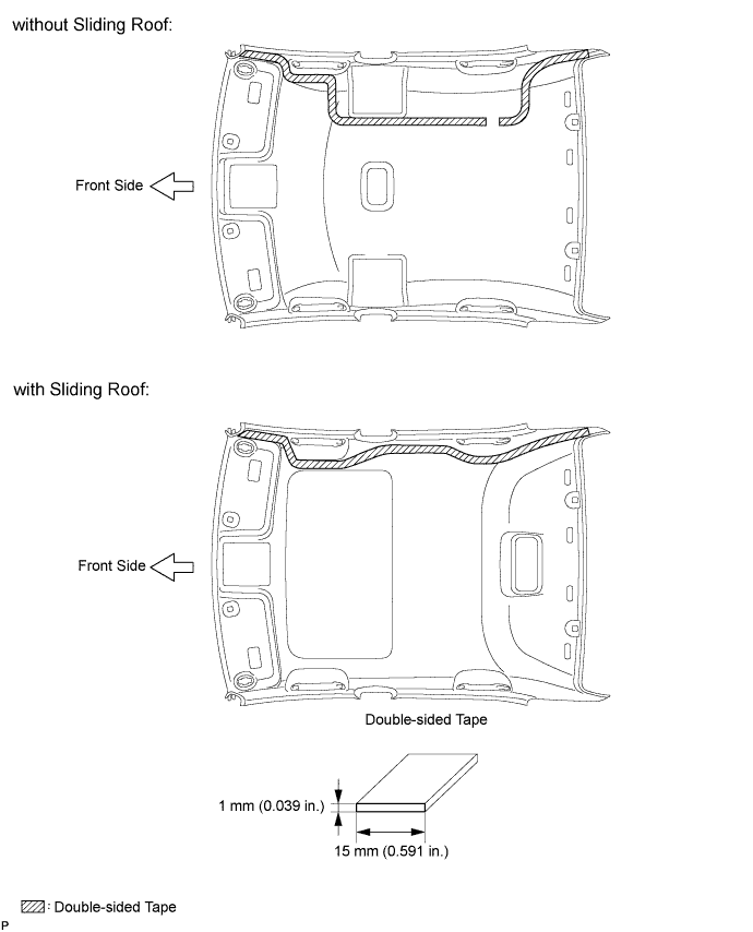
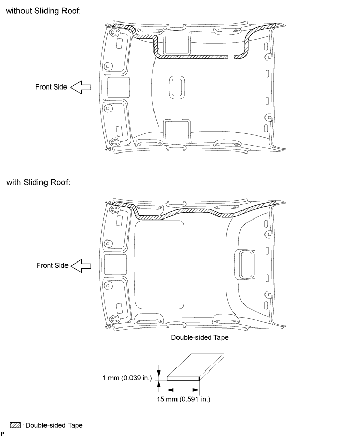
Apply new double-sided tape to the locations shown in the illustration while aligning the tape with the markings on the roof headlining.
NOTICE:
Securely apply the double-sided tape to prevent it from being out of alignment and peeling off.
Peel off the release paper from the double-sided tape.
Attach the No. 1 roof wire along the double-sided tape so that the marking surface of the wire harness faces downward.
NOTICE:
Securely attach the No. 1 roof wire. Failure to do so may cause abnormal noise.
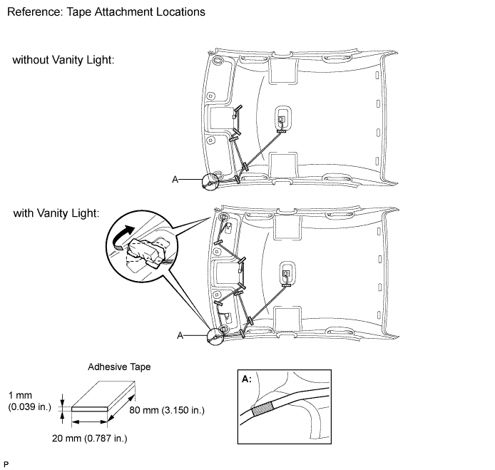
Vanity Light:
Turn the visor connectors clockwise approximately 90° to install the connectors to the roof headlining.
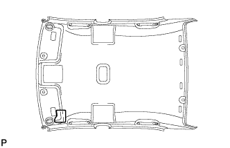
Apply adhesive tape to the locations shown in the illustration.
HINT:
As shown at point A in the illustration, line up and secure the reference tape of the wire harness to the tip of the roof headlining assembly.
2.
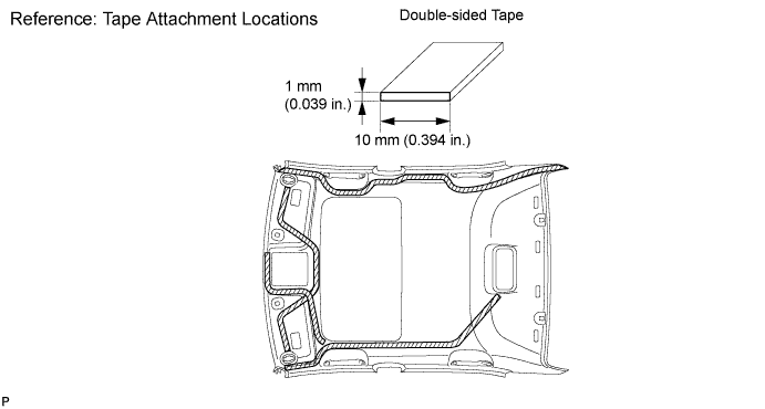
INSTALL NO. 1 ROOF WIRE (w/ Sliding Roof)
Apply new double-sided tape to the locations shown in the illustration while aligning the tape with the markings on the roof headlining.
NOTICE:
Securely apply the double-sided tape to prevent it from being out of alignment and peeling off.
Peel off the release paper from the double-sided tape.
Attach the No. 1 roof wire along the double-sided tape so that the marking surface of the wire harness faces downward.
NOTICE:
Securely attach the No. 1 roof wire. Failure to do so may cause abnormal noise.
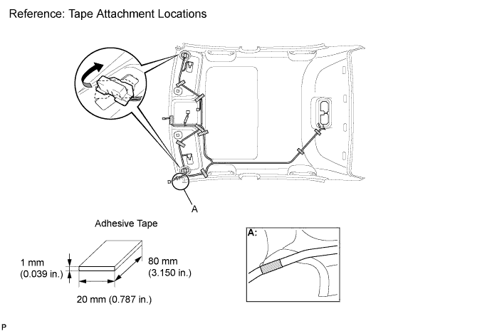
Turn the visor connectors clockwise approximately 90° to install the connectors to the roof headlining.
Apply adhesive tape to the locations shown in the illustration.
HINT:
As shown at point A in the illustration, line up and secure the reference tape of the wire harness to the tip of the roof headlining assembly.
3.
INSTALL ANTENNA CORD SUB-ASSEMBLY (for 2GR-FE RHD)
HINT:
The double-sided tape and tape are not available as supply parts. If these tapes still have enough adhesion to secure the roof headlining and antenna cord, reuse the tapes. If the roof headlining has been replaced with a new one, or if the tape and/or the double-sided tape is no longer sticky, apply new tape following the procedures below.
Apply new double-sided tape.
Remove the double-sided tape from the roof headlining assembly.
Peel off the appropriate amount of new double-sided tape. Be careful not to touch the adhesive surface.
Apply the double-sided tape to the roof headlining while aligning the tape with the markings on the roof headlining assembly.
Peel off the backing sheet from the double-sided tape.
Install the antenna cord to the roof headlining assembly from the front of the vehicle.
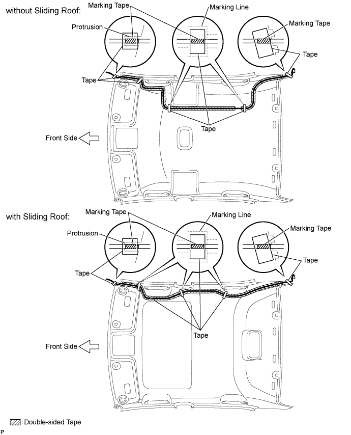
Put the strips of the tape back to the positions shown in the illustration in order to secure the antenna cord to the roof headlining assembly.
HINT:
If the tape is no longer sticky, use other tape, such as packing tape, that has enough adhesion to secure the antenna cord to the roof headlining assembly.
For the right front corner of the roof headlining assembly, align the marking tape on the antenna cord with the protrusion of the roof headlining, and wrap tape around the antenna cord and roof headlining assembly once or twice to securely hold them.
For the right rear corner of the roof headlining assembly, align the marking tape on the antenna cord with the rear edge of the roof headlining, and secure the antenna cord to the roof headlining assembly with tape.
For the part of the antenna cord near the center of the roof headlining assembly, position the marking tape on the antenna cord within the area indicated by the marking line. Secure the antenna cord to the roof headlining assembly with tape as shown in the illustration.
4.
INSTALL ANTENNA CORD SUB-ASSEMBLY (except 2GR-FE RHD)
HINT:
The double-sided tape and tape are not available as supply parts. If these tapes still have enough adhesion to secure the roof headlining and antenna cord, reuse the tapes. If the roof headlining has been replaced with a new one, or if the tape and/or the double-sided tape is no longer sticky, apply new tape following the procedures below.
Apply new double-sided tape.
Remove the double-sided tape from the roof headlining assembly.
Peel off the appropriate amount of new double-sided tape. Be careful not to touch the adhesive surface.
Apply the double-sided tape to the roof headlining while aligning the tape with the markings on the roof headlining assembly.
Peel off the backing sheet from the double-sided tape.
Install the antenna cord to the roof headlining assembly from the front of the vehicle.
Put the strips of the tape back to the positions shown in the illustration in order to secure the antenna cord to the roof headlining assembly.
HINT:
If the tape is no longer sticky, use other tape, such as packing tape, that has enough adhesion to secure the antenna cord to the roof headlining assembly.
For the right front corner of the roof headlining assembly, align the marking tape on the antenna cord with the protrusion of the roof headlining, and wrap tape around the antenna cord and roof headlining assembly once or twice to securely hold them.
For the right rear corner of the roof headlining assembly, align the marking tape on the antenna cord with the rear edge of the roof headlining, and secure the antenna cord to the roof headlining assembly with tape.
For the part of the antenna cord near the center of the roof headlining assembly, position the marking tape on the antenna cord within the area indicated by the marking line. Secure the antenna cord to the roof headlining assembly with tape as shown in the illustration.
5.
INSTALL VANITY LIGHT ASSEMBLY
Engage the 3 claws and install the vanity light assembly.
6.
INSTALL NO. 4 ROOF SILENCER PAD (w/o Sliding Roof)
Align the markings on the roof headlining assembly with the No. 4 roof silencer pads and install the silencer pads using hot melt glue or double-sided tape as shown in the illustration.
7.
INSTALL NO. 2 ROOF SILENCER PAD (w/o Sliding Roof)
Align the markings on the roof headlining assembly with the No. 2 roof silencer pad and install the silencer pad using hot melt glue or double-sided tape as shown in the illustration.
8.
INSTALL ROOF SIDE RAIL SILENCER PAD LH (w/o Sliding Roof)
Align the markings on the roof headlining assembly with the roof side rail silencer pad LH and install the silencer pad using hot melt glue as shown in the illustration. (with Curtain Shield Airbag)
9.
INSTALL ROOF SIDE RAIL SILENCER PAD RH (w/o Sliding Roof)
HINT:
Use the same procedures for the RH side and the LH side.
10.
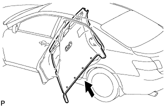
INSTALL ROOF HEADLINING ASSEMBLY (w/o Sliding Roof)
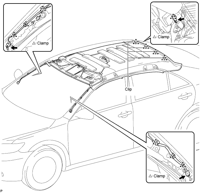
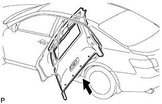
Pull the roof headlining assembly into the vehicle through the rear left door. Engage the 4 clips.
Connect the antenna cord sub-assembly connector and engage the clamp to the rear pillar RH.
Connect the antenna cord sub-assembly connector and engage each clamp to the front pillar RH.
Install the radio setting condenser to the front pillar RH with the bolt.
Connect the No. 1 roof wire connector and engage each clamp to the front pillar LH.
11.
INSTALL ROOF HEADLINING ASSEMBLY (w/ Sliding Roof)
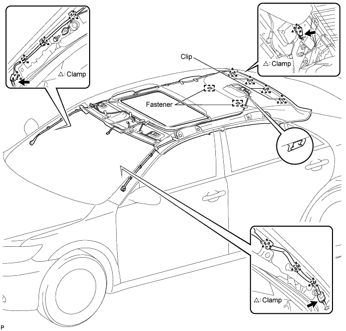
Pull the roof headlining assembly into the vehicle through the rear left door. Engage the hook, 4 clips, and 2 fasteners.
Connect the sliding roof drive gear connector.
Connect the antenna cord sub-assembly connector and engage the clamp to the rear pillar RH.
Connect the antenna cord sub-assembly connector and engage each clamp to the front pillar RH.
Install the radio setting condenser to the front pillar RH with the bolt.
Connect the No. 1 roof wire connector and engage each clamp to the front pillar LH.
12.
INSTALL SUN ROOF OPENING TRIM MOULDING (w/ Sliding Roof)
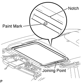
Align the paint mark on the inner surface of the opening trim moulding with the notch of the roof headlining, and install the sun roof opening trim moulding so that the joining point of the opening trim is on the left side of the vehicle as shown in the illustration.
NOTICE:
After installation, check that the corners fit correctly.
13.
INSTALL SPOT LIGHT ASSEMBLY (w/ Sliding Roof)
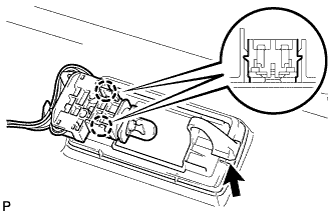
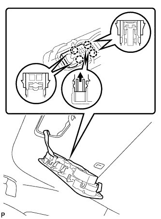
Push the light bulb holder in the direction indicated by the arrow in the illustration to engage the claw. Engage the 4 claws.
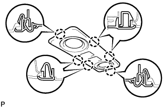
Engage the 6 claws and install the spot light assembly.
14.
INSTALL NO. 1 ROOM LIGHT ASSEMBLY (w/o Sliding Roof)
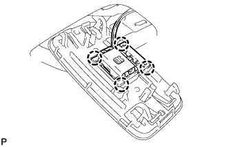
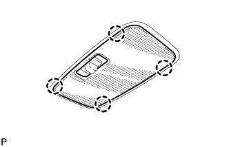
Engage the 4 claws and install the room light switch base to the No. 1 room light assembly.
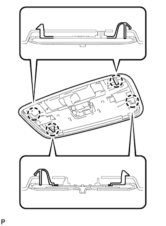
Engage the 4 claws.
Engage the 4 claws and install the lens cover.
15.
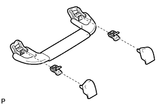
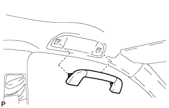
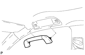
INSTALL FRONT ASSIST GRIP SUB-ASSEMBLY (for Driver Side)
with Assist Grip:
Assemble the front assist grip sub-assembly as shown in the illustration.
Install the front assist grip sub-assembly.
16.
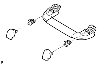
INSTALL FRONT ASSIST GRIP SUB-ASSEMBLY (for Front Passenger Side)
Assemble the front assist grip sub-assembly as shown in the illustration.
Install the front assist grip sub-assembly.
17.
INSTALL REAR ASSIST GRIP SUB-ASSEMBLY
HINT:
Use the same procedure for the rear side and the front side.
18.
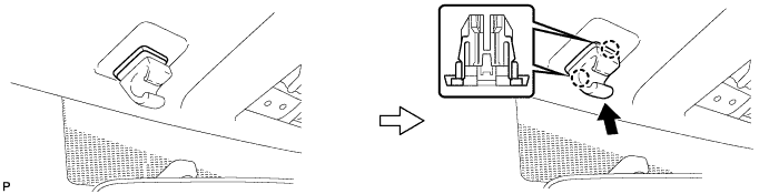
INSTALL VISOR HOLDER
Engage the 2 claws.
Push in the visor holder as shown in the illustration.
HINT:
Use the same procedure for the RH side and the LH side.
19.
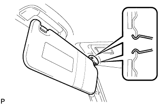
INSTALL VISOR ASSEMBLY LH
Engage the 2 clips and install the visor assembly LH.
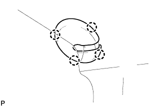
Engage the 4 claws and install the visor bracket cover.
20.
INSTALL VISOR ASSEMBLY RH
HINT:
Use the same procedure for the RH side and the LH side.
21.
INSTALL ROOF CONSOLE BOX ASSEMBLY
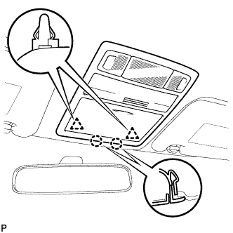
Connect the connectors. Engage the 2 claws and 2 clips, and then install the roof console box assembly.
22.
INSTALL RAIN SENSOR COVER (w/ Rain Sensor)
Install the rain sensor cover.
23.
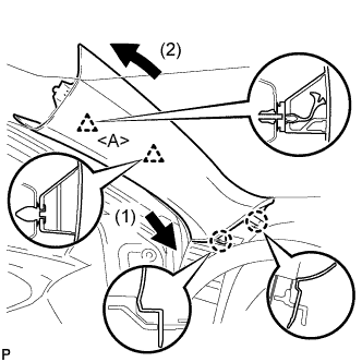
INSTALL FRONT PILLAR GARNISH LH (w/o Curtain Shield Airbag)
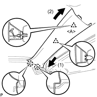
Install a new clip <A> on the front pillar garnish LH. Engage the 2 claws and 2 clips, then install the front pillar garnish LH.
24.
INSTALL FRONT PILLAR GARNISH LH (w/ Curtain Shield Airbag)
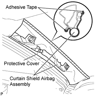
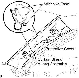
Remove the protective cover.
Install a new clip <A> on the front pillar garnish LH. Engage the 2 claws and 2 clips, then install the front pillar garnish LH.
25.
INSTALL FRONT PILLAR GARNISH RH (w/o Curtain Shield Airbag)
Install a new clip <A> on the front pillar garnish RH. Engage the 2 claws and 2 clips, then install the front pillar garnish RH.
26.
INSTALL FRONT PILLAR GARNISH RH (w/ Curtain Shield Airbag)
Remove the protective cover.
Install a new clip <A> on the front pillar garnish RH. Engage the 2 claws and 2 clips, then install the front pillar garnish RH.
27.
INSTALL ROOF SIDE INNER GARNISH LH
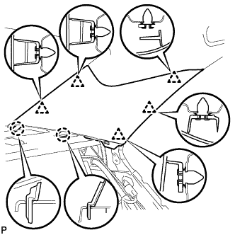
Engage the 5 clips and 2 claws, then install the roof side inner garnish LH.
28.
INSTALL ROOF SIDE INNER GARNISH RH
HINT:
Use the same procedure for the RH side and the LH side.
29.
INSTALL UPPER CENTER PILLAR GARNISH LH
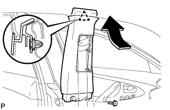
Engage the clip. Install the upper center pillar garnish LH with the bolt.
30.
INSTALL LOWER CENTER PILLAR GARNISH LH
Engage the 2 claws and 2 clips, then install the lower center pillar garnish LH.
31.
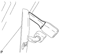
CONNECT FRONT SEAT OUTER BELT ASSEMBLY LH
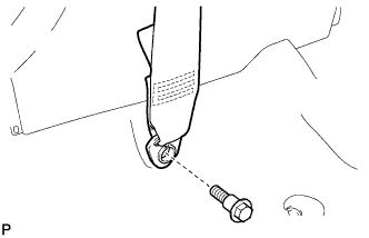
Install the floor end of the front seat outer belt assembly LH with the bolt.
Torque:
42 N*m{
428 kgf*cm
, 31 ft.*lbf
}
32.
INSTALL LAP BELT OUTER ANCHOR COVER (for LH Side)
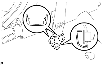
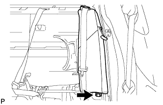
Engage the 3 claws and install the lap belt outer anchor cover.
33.
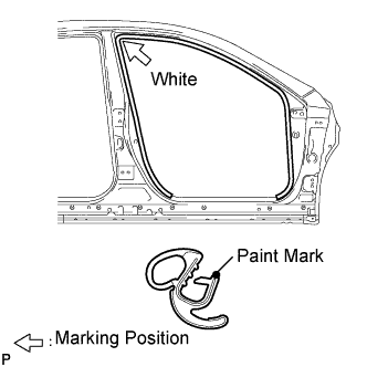
INSTALL FRONT DOOR OPENING TRIM WEATHERSTRIP LH
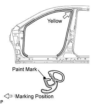
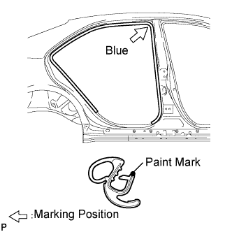
Install the front door opening trim weatherstrip LH as shown in the illustration.
NOTICE:
After installation, check that the corners fit correctly.
34.
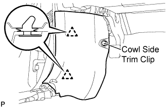
INSTALL COWL SIDE TRIM SUB-ASSEMBLY LH
Engage the 2 clips. Install the cowl side trim sub-assembly LH with the cowl side trim clip.
35.
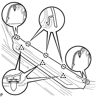
INSTALL FRONT DOOR SCUFF PLATE LH
Engage the 7 claws and 3 clips, then install the front door scuff plate LH.
36.
INSTALL UPPER CENTER PILLAR GARNISH RH
HINT:
Use the same procedure for the RH side and the LH side.
37.
INSTALL LOWER CENTER PILLAR GARNISH RH
HINT:
Use the same procedure for the RH side and the LH side.
38.
CONNECT FRONT SEAT OUTER BELT ASSEMBLY RH
HINT:
Use the same procedure for the RH side and the LH side.
39.
INSTALL LAP BELT OUTER ANCHOR COVER (for RH Side)
HINT:
Use the same procedure for the RH side and the LH side.
40.
INSTALL FRONT DOOR OPENING TRIM WEATHERSTRIP RH
Install the front door opening trim weatherstrip RH as shown in the illustration.
NOTICE:
After installation, check that the corners fit correctly.
41.
INSTALL COWL SIDE TRIM SUB-ASSEMBLY RH
HINT:
Use the same procedure for the RH side and the LH side.
42.
INSTALL FRONT DOOR SCUFF PLATE RH
HINT:
Use the same procedure for the RH side and the LH side.
43.
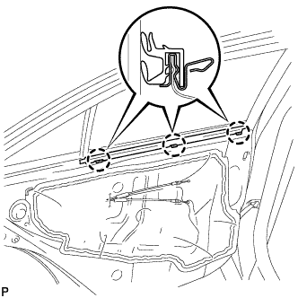
INSTALL REAR DOOR INNER GLASS WEATHERSTRIP LH
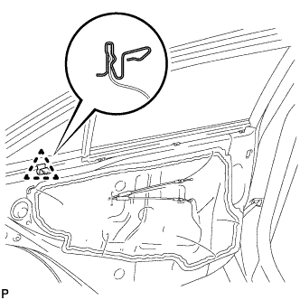
Engage the 3 claws to install the rear door inner glass weatherstrip.
44.
INSTALL REAR DOOR TRIM BOARD SUB-ASSEMBLY LH
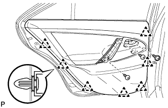
Engage the claw to install the No. 1 door scuff plate clamp. Connect each connector.
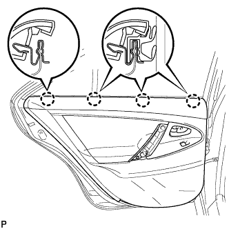
Engage the rear door trim board with the 4 clips of the rear door inner glass weatherstrip.
Engage the 7 clips to install the rear door trim board to the rear door panel. Install the 3 screws.
45.
INSTALL COURTESY LIGHT ASSEMBLY (w/ Courtesy Light)
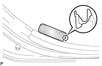
Connect the connector.
Engage the claw and install the courtesy light assembly.
46.
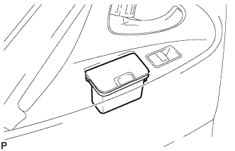
INSTALL REAR ASH RECEPTACLE ASSEMBLY LH (w/ Ashtray)
Install the rear ash receptacle assembly.
47.
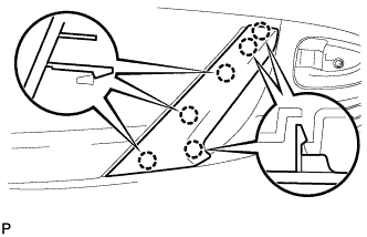
INSTALL DOOR ASSIST GRIP COVER LH
Engage the 6 claws and install the door assist grip cover.
48.
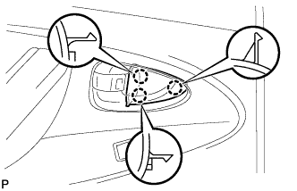
INSTALL REAR DOOR INSIDE HANDLE BEZEL PLUG LH
Engage the 3 claws to install the rear door inside handle bezel plug.
49.
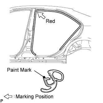
INSTALL REAR DOOR OPENING TRIM WEATHERSTRIP LH
Install the rear door opening trim weatherstrip LH as shown in the illustration.
NOTICE:
After installation, check that the corners fit correctly.
50.
INSTALL REAR DOOR SCUFF PLATE LH
Engage the 5 claws and 2 clips, then install the rear door scuff plate LH.
51.
INSTALL REAR DOOR OPENING TRIM WEATHERSTRIP RH
Install the rear door opening trim weatherstrip RH as shown in the illustration.
NOTICE:
After installation, check that the corners fit correctly.
52.
INSTALL REAR DOOR SCUFF PLATE RH
HINT:
Use the same procedure for the RH side and the LH side.
53.
INSTALL REAR SIDE SEATBACK ASSEMBLY LH (for Fold Down Seat Type)
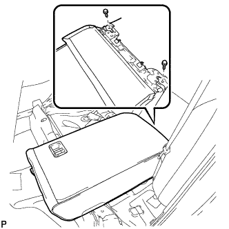
Install the rear side seatback assembly with the bolt.
Torque:
18 N*m{
184 kgf*cm
, 13 ft.*lbf
}
54.
INSTALL REAR SIDE SEATBACK ASSEMBLY RH (for Fold Down Seat Type)
HINT:
Use the same procedure for the RH side and the LH side.
55.
INSTALL SEPARATE TYPE REAR SEATBACK ASSEMBLY LH (for Fold Down Seat Type)
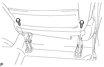
Install the separate type rear seatback assembly with the 2 bolts.
Torque:
18 N*m{
184 kgf*cm
, 13 ft.*lbf
}
56.
INSTALL SEPARATE TYPE REAR SEATBACK ASSEMBLY RH (for Fold Down Seat Type)
Install the separate type rear seatback assembly with the 2 bolts.
Torque:
18 N*m{
184 kgf*cm
, 13 ft.*lbf
}
57.
INSTALL REAR SEATBACK ASSEMBLY (for Fixed Seat Type)
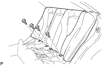
Place the seatback in the cabin.
NOTICE:
Be careful not to damage the vehicle body.
Install the rear seatback assembly with the 4 bolts.
Torque:
18 N*m{
184 kgf*cm
, 13 ft.*lbf
}
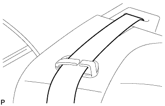
Pass the 3 seat belts through and close the cap of the 2 rear seat shoulder belt guides. Install the floor anchor part with the bolt.
58.
INSTALL REAR CENTER SEAT HEADREST ASSEMBLY (w/ Center Armrest)
59.
INSTALL REAR SEAT HEADREST ASSEMBLY
60.
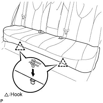
INSTALL REAR SEAT CUSHION ASSEMBLY (for Fixed Seat Type)
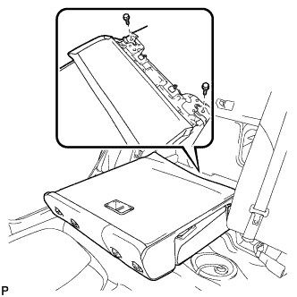
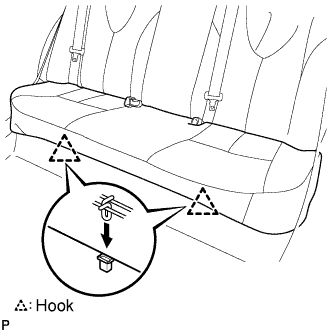
Attach the 2 front hooks of the seat cushion to the vehicle body. Confirm that the seat cushion is firmly installed.
NOTICE:
When installing the seat cushion, make sure the seat belt buckle is not under the seat cushion.
61.
INSTALL REAR SEAT CUSHION ASSEMBLY (for Fold Down Seat Type)
Attach the front hooks of the bench type rear seat cushion assembly to the vehicle body. Confirm that the seat cushion is firmly installed.
NOTICE:
When installing the bench type rear seat cushion assembly, make sure that the seat belt buckle is not under the bench type rear seat cushion assembly.
62.
INSTALL FRONT SEAT ASSEMBLY LH (for 2AZ-FE Power Seat)
Place the seat in the cabin.
Connect the connectors under the seat.
Connect the cable to the negative (-) battery terminal.
Move the front seat assembly to the rearmost position by operating the slide and vertical power seat switch knob.
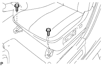
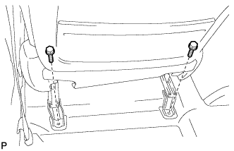
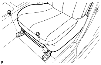
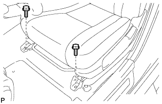
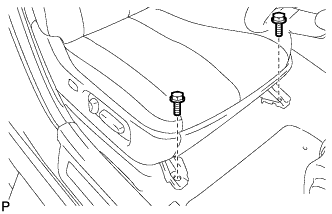
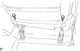
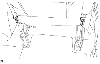
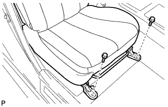
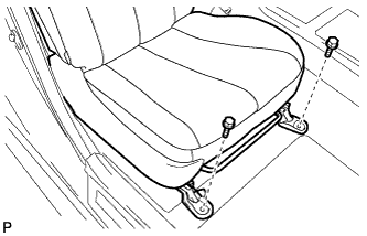
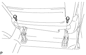
Temporarily install the front side of the front seat assembly with the 2 bolts. Move the front seat assembly fully forward by operating the slide and vertical power seat switch knob.
Temporarily install the rear side of the front seat assembly with the 2 bolts. Move the front seat assembly to the rearmost position by operating the slide and vertical power seat switch knob.
Fully tighten the 2 bolts on the front side of the front seat assembly in the order of the inner side bolt and then the outer side bolt.
Torque:
37 N*m{
377 kgf*cm
, 27 ft.*lbf
}
Move the front seat assembly fully forward by operating the slide and vertical power seat switch knob.
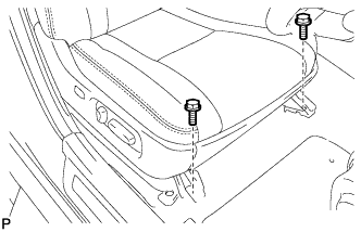
Fully tighten the 2 bolts on the rear side of the front seat assembly in the order of the inner side bolt and then the outer side bolt.
Torque:
37 N*m{
377 kgf*cm
, 27 ft.*lbf
}
63.
INSTALL INNER SEAT TRACK BRACKET COVER LH (for 2AZ-FE Power Seat)
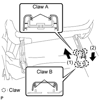
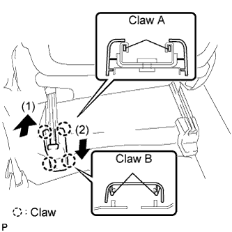
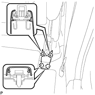
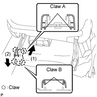
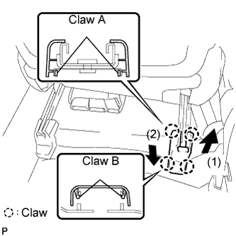
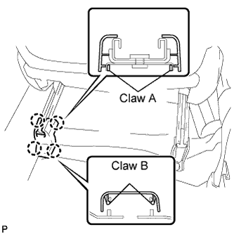
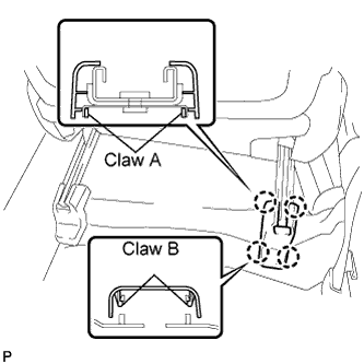
Slide the inner seat track bracket cover along the seat rail toward the front of the vehicle. Engage claw A to the seat rail. Push the inner seat track bracket cover to engage claw B.
64.
INSTALL OUTER SEAT TRACK BRACKET COVER LH (for 2AZ-FE Power Seat)
Slide the outer seat track bracket cover along the seat rail toward the front of the vehicle. Engage claw A to the seat rail. Push the seat track cover to engage claw B.
65.
INSTALL FRONT SEAT HEADREST ASSEMBLY (for 2AZ-FE Power Seat)
66.
INSTALL FRONT SEAT ASSEMBLY LH (for 2GR-FE LHD Power Seat)
Place the seat in the cabin.
Connect the connectors under the seat.
Connect the cable to the negative (-) battery terminal.
Move the front seat assembly to the rearmost position by operating the slide and vertical power seat switch knob.
Temporarily install the front side of the front seat assembly with the 2 bolts. Move the front seat assembly fully forward by operating the slide and vertical power seat switch knob.
Temporarily install the rear side of the front seat assembly with the 2 bolts. Move the front seat assembly to the rearmost position by operating the slide and vertical power seat switch knob.
Fully tighten the 2 bolts on the front side of the front seat assembly in the order of the inner side bolt and then the outer side bolt.
Torque:
37 N*m{
377 kgf*cm
, 27 ft.*lbf
}
Move the front seat assembly fully forward by operating the slide and vertical power seat switch knob.
Fully tighten the 2 bolts on the rear side of the front seat assembly in the order of the inner side bolt and then the outer side bolt.
Torque:
37 N*m{
377 kgf*cm
, 27 ft.*lbf
}
67.
INSTALL INNER SEAT TRACK BRACKET COVER LH (for 2GR-FE LHD Power Seat)
Slide the inner seat track bracket cover along the seat rail toward the front of the vehicle. Engage claw A to the seat rail. Push the inner seat track bracket cover to engage claw B.
68.
INSTALL OUTER SEAT TRACK BRACKET COVER LH (for 2GR-FE LHD Power Seat)
Slide the outer seat track bracket cover along the seat rail toward the front of the vehicle. Engage claw A to the seat rail. Push the seat track cover to engage claw B.
69.
INSTALL FRONT SEAT HEADREST ASSEMBLY (for 2GR-FE LHD Power Seat)
70.
INSTALL FRONT SEAT ASSEMBLY LH (for 2GR-FE RHD Power Seat)
HINT:
Use the same procedure for the RH side and the LH side.
71.
INSTALL INNER SEAT TRACK BRACKET COVER LH (for 2GR-FE RHD Power Seat)
HINT:
Use the same procedure for the RH side and the LH side.
72.
INSTALL OUTER SEAT TRACK BRACKET COVER LH (for 2GR-FE RHD Power Seat)
HINT:
Use the same procedure for the RH side and the LH side.
73.
INSTALL FRONT SEAT HEADREST ASSEMBLY (for 2GR-FE RHD Power Seat)
74.
INSTALL FRONT SEAT ASSEMBLY LH (for 2AZ-FE Manual Seat)
Place the front seat assembly in the vehicle and align the adjuster pin with the hole on the vehicle side.
Connect the connector and clamp.
Move the front seat assembly to the rearmost position by operating the slide handle.
NOTICE:
Check that the seat is locked.
Temporarily install the front seat track bracket with the 2 bolts. Move the front seat assembly fully forward by operating the slide handle.
NOTICE:
Check that the seat is locked.
Temporarily install the rear seat track bracket with the 2 bolts. Move the front seat assembly to the rearmost position by operating the slide handle.
NOTICE:
Check that the seat is locked.
Fully tighten the 2 bolts on the front seat track bracket in the order of the inner side bolt and then the outer side bolt.
Torque:
37 N*m{
377 kgf*cm
, 27 ft.*lbf
}
Move the front seat assembly fully forward by operating the slide handle.
NOTICE:
Check that the seat is locked.
Fully tighten the 2 bolts on the rear seat track bracket in the order of the inner side bolt and then the outer side bolt.
Torque:
37 N*m{
377 kgf*cm
, 27 ft.*lbf
}
75.
INSTALL INNER SEAT TRACK BRACKET COVER LH (for 2AZ-FE Manual Seat)
Slide the inner seat track bracket cover along the seat rail toward the front of the vehicle. Engage claw A to the seat rail. Push the inner seat track bracket cover inner to engage claw B.
76.
INSTALL OUTER SEAT TRACK BRACKET COVER LH (for 2AZ-FE Manual Seat)
Slide the outer seat track bracket cover along the seat rail toward the front of the vehicle. Engage claw A to the seat rail. Push the outer seat track bracket cover to engage claw B.
77.
INSTALL FRONT SEAT HEADREST ASSEMBLY (for 2AZ-FE Manual Seat)
78.
INSTALL FRONT SEAT ASSEMBLY LH (for 2GR-FE RHD Manual Seat)
Place the front seat assembly in the vehicle and align the adjuster pin with the hole on the vehicle side.
Connect the connector and clamp.
Move the front seat assembly to the rearmost position by operating the slide handle.
NOTICE:
Check that the seat is locked.
Temporarily install the front seat track bracket with the 2 bolts. Move the front seat assembly fully forward by operating the slide handle.
NOTICE:
Check that the seat is locked.
Temporarily install the rear seat track bracket with the 2 bolts. Move the front seat assembly to the rearmost position by operating the slide handle.
NOTICE:
Check that the seat is locked.
Fully tighten the 2 bolts on the front seat track bracket in the order of the inner side bolt and then the outer side bolt.
Torque:
37 N*m{
377 kgf*cm
, 27 ft.*lbf
}
Move the front seat assembly fully forward by operating the slide handle.
NOTICE:
Check that the seat is locked.
Fully tighten the 2 bolts on the rear seat track bracket in the order of the inner side bolt and then the outer side bolt.
Torque:
37 N*m{
377 kgf*cm
, 27 ft.*lbf
}
79.
INSTALL INNER SEAT TRACK BRACKET COVER LH (for 2GR-FE RHD Manual Seat)
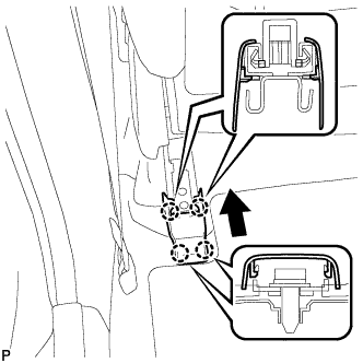
Engage the 4 claws and install the front seat rear inner track bracket cover.
80.
INSTALL OUTER SEAT TRACK BRACKET COVER LH (for 2GR-FE RHD Manual Seat)
Engage the 4 claws and install the front seat rear outer track bracket cover.
81.
REMOVE FRONT SEAT HEADREST ASSEMBLY (for 2GR-FE RHD Manual Seat)
82.
INSTALL FRONT SEAT ASSEMBLY RH (for 2AZ-FE Power Seat)
HINT:
Use the same procedure for the RH side and the LH side.
83.
INSTALL INNER SEAT TRACK BRACKET COVER RH (for 2AZ-FE Power Seat)
HINT:
Use the same procedure for the RH side and the LH side.
84.
INSTALL OUTER SEAT TRACK BRACKET COVER RH (for 2AZ-FE Power Seat)
HINT:
Use the same procedure for the RH side and the LH side.
85.
INSTALL FRONT SEAT HEADREST ASSEMBLY (for 2AZ-FE Power Seat)
86.
INSTALL FRONT SEAT ASSEMBLY RH (for 2GR-FE LHD Power Seat)
Place the seat in the cabin.
Connect the connectors under the seat.
Connect the cable to the negative (-) battery terminal.
Move the front passenger's seat assembly to the rearmost position by operating the slide and vertical power seat switch knob.
Temporarily install the front side of the front passenger's seat assembly with the 2 bolts. Move the front passenger's seat assembly fully forward by operating the slide and vertical power seat switch knob.
Temporarily install the rear side of the front passenger's seat assembly with the 2 bolts. Move the front passenger's seat assembly to the rearmost position by operating the slide and vertical power seat switch knob.
Fully tighten the 2 bolts on the front side of the front passenger's seat assembly in the order of the inner side bolt and then the outer side bolt.
Torque:
37 N*m{
377 kgf*cm
, 27 ft.*lbf
}
Move the front passenger's seat assembly fully forward by operating the slide and vertical power seat switch knob.
Fully tighten the 2 bolts on the rear side of the front passenger's seat assembly in the order of the inner side bolt and then the outer side bolt.
Torque:
37 N*m{
377 kgf*cm
, 27 ft.*lbf
}
87.
INSTALL INNER SEAT TRACK BRACKET COVER RH (for 2GR-FE LHD Power Seat)
Engage the 4 claws and install the inner seat track bracket cover.
88.
INSTALL OUTER SEAT TRACK BRACKET COVER RH (for 2GR-FE LHD Power Seat)
Engage the 4 claws and install the outer seat track bracket cover.
89.
INSTALL FRONT SEAT HEADREST ASSEMBLY (for 2GR-FE LHD Power Seat)
90.
INSTALL FRONT SEAT ASSEMBLY RH (for 2GR-FE RHD Power Seat)
Place the seat in the cabin.
Connect the connectors under the seat.
Connect the cable to the negative (-) battery terminal.
Move the front seat assembly to the rearmost position by operating the slide and vertical power seat switch knob.
Temporarily install the front side of the front seat assembly with the 2 bolts. Move the front seat assembly fully forward by operating the slide and vertical power seat switch knob.
Temporarily install the rear side of the front seat assembly with the 2 bolts. Move the front seat assembly to the rearmost position by operating the slide and vertical power seat switch knob.
Fully tighten the 2 bolts on the front side of the front seat assembly in the order of the inner side bolt and then the outer side bolt.
Torque:
37 N*m{
377 kgf*cm
, 27 ft.*lbf
}
Move the front seat assembly fully forward by operating the slide and vertical power seat switch knob.
Fully tighten the 2 bolts on the rear side of the front seat assembly in the order of the inner side bolt and then the outer side bolt.
Torque:
37 N*m{
377 kgf*cm
, 27 ft.*lbf
}
91.
INSTALL INNER SEAT TRACK BRACKET COVER RH (for 2GR-FE RHD Power Seat)
Engage the 4 claws and install the front seat rear inner track bracket cover.
92.
INSTALL OUTER SEAT TRACK BRACKET COVER RH (for 2GR-FE RHD Power Seat)
Engage the 4 claws and install the front seat rear outer track bracket cover.
93.
INSTALL FRONT SEAT HEADREST ASSEMBLY (for 2GR-FE RHD Power Seat)
94.
INSTALL FRONT SEAT ASSEMBLY RH (for 2AZ-FE Manual Seat)
Place the front passenger's seat assembly in the vehicle and align the adjuster pin with the hole on the vehicle side.
Connect the connectors and clamp.
Move the front passenger's seat assembly to the rearmost position by operating the slide handle.
NOTICE:
Check that the seat is locked.
Temporarily install the front seat track bracket with the 2 bolts. Move the front passenger's seat assembly fully forward by operating the slide handle.
NOTICE:
Check that the seat is locked.
Temporarily install the rear seat track bracket with the 2 bolts. Move the front passenger's seat assembly to the rearmost position by operating the slide handle.
NOTICE:
Check that the seat is locked.
Fully tighten the 2 bolts on the front seat track bracket in the order of the inner side bolt and then the outer side bolt.
Torque:
37 N*m{
377 kgf*cm
, 27 ft.*lbf
}
Move the front passenger's seat assembly fully forward by operating the slide handle.
NOTICE:
Check that the seat is locked.
Fully tighten the 2 bolts on the rear seat track bracket in the order of the inner side bolt and then the outer side bolt.
Torque:
37 N*m{
377 kgf*cm
, 27 ft.*lbf
}
95.
INSTALL INNER SEAT TRACK BRACKET COVER RH (for 2AZ-FE Manual Seat)
Slide the inner seat track bracket cover along the seat rail toward the front of the vehicle. Engage claw A to the seat rail. Push the inner seat track bracket cover to engage claw B.
96.
INSTALL OUTER SEAT TRACK BRACKET COVER RH (for 2AZ-FE Manual Seat)
Slide the outer seat track bracket cover along the seat rail toward the front of the vehicle. Engage claw A to the seat rail. Push the outer seat track bracket cover to engage claw B.
97.
INSTALL FRONT SEAT HEADREST ASSEMBLY (for 2AZ-FE Manual Seat)
98.
INSTALL FRONT SEAT ASSEMBLY RH (for 2GR-FE LHD Manual Seat)
Place the front seat assembly in the vehicle and align the adjuster pin with the hole on the vehicle side.
Connect the connector and clamp.
Move the front seat assembly to the rearmost position by operating the slide handle.
NOTICE:
Check that the seat is locked.
Temporarily install the front seat track bracket with the 2 bolts. Move the front seat assembly fully forward by operating the slide handle.
NOTICE:
Check that the seat is locked.
Temporarily install the rear seat track bracket with the 2 bolts. Move the front seat assembly to the rearmost position by operating the slide handle.
NOTICE:
Check that the seat is locked.
Fully tighten the 2 bolts on the front seat track bracket in the order of the inner side bolt and then the outer side bolt.
Torque:
37 N*m{
377 kgf*cm
, 27 ft.*lbf
}
Move the front seat assembly fully forward by operating the slide handle.
NOTICE:
Check that the seat is locked.
Fully tighten the 2 bolts on the rear seat track bracket in the order of the inner side bolt and then the outer side bolt.
Torque:
37 N*m{
377 kgf*cm
, 27 ft.*lbf
}
99.
INSTALL INNER SEAT TRACK BRACKET COVER RH (for 2GR-FE LHD Manual Seat)
Slide the inner seat track bracket cover along the seat rail toward the front of the vehicle. Engage claw A to the seat rail. Push the seat track bracket cover inner to engage claw B.
100.
INSTALL OUTER SEAT TRACK BRACKET COVER RH (for 2GR-FE LHD Manual Seat)
Slide the seat track cover along the seat rail toward the front of the vehicle. Engage claw A to the seat rail. Push the seat track cover to engage claw B.
101.
REMOVE FRONT SEAT HEADREST ASSEMBLY (for 2GR-FE LHD Manual Seat)
102.
CONNECT CABLE TO NEGATIVE BATTERY TERMINAL (for Manual Seat)
103.
INSPECT SRS WARNING LIGHT
(Click here )
104.
INSPECT FRONT SEAT ASSEMBLY (for 2AZ-FE Power Seat)
Inspect the power seat operation.
105.
INSPECT FRONT SEAT ASSEMBLY (for 2GR-FE LHD Power Seat)
Inspect the power seat operation.
106.
INSPECT FRONT SEAT ASSEMBLY (for 2GR-FE RHD Power Seat)
Inspect the power seat operation.
107.
INSPECT SLIDE ADJUSTER LOCK (for Manual Seat)