Removal / installation · Vehicles built Oct 2006 – May 2009
Versions by build date: Oct 2006 – May 2009from Jun 2009
1.
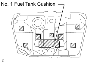
INSTALL NO. 1 FUEL TANK CUSHION
Install a new No. 1 fuel tank cushion to the fuel tank.
2.
INSTALL NO. 2 FUEL TANK CUSHION
Install 7 new No. 2 fuel tank cushions to the fuel tank.
3.
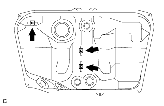
INSTALL NO. 4 FUEL TUBE CLAMP
Install the 3 clamps.
4.
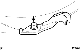
INSTALL FUEL MAIN TUBE SUPPORT
Install the fuel main tube support with the bolt.
Torque:
5.4 N*m{
55 kgf*cm
, 48 in.*lbf
}
5.
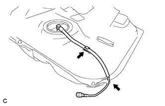
INSTALL FUEL PUMP TUBE SUB-ASSEMBLY
Install the fuel pump tube to the fuel main tube support and the clamp.
6.
INSTALL FUEL CUT OFF WITH TUBE VALVE ASSEMBLY
Install 2 new gaskets to the fuel tank.
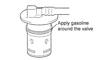
Apply a light coat of spindle oil or gasoline around 2 new fuel cut off valves as shown in the illustration, and carefully insert them into the tank. Be careful not to drop the gasket into the tank.
Check that the fuel cut off valve is fully inserted.
7.
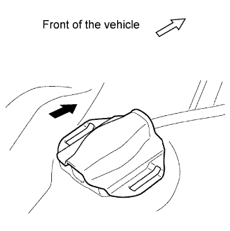
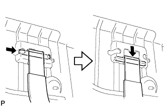
INSTALL NO. 3 FUEL TANK PROTECTOR
Install the No. 3 fuel tank protector by sliding it as shown in the illustration.
8.
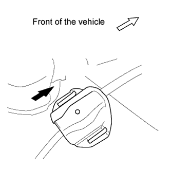
INSTALL NO. 2 FUEL TANK PROTECTOR
Install the No. 2 fuel tank protector by sliding it as shown in the illustration.
9.
INSTALL FUEL TANK ASSEMBLY
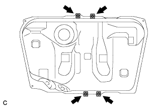
Install the 4 clip nuts.
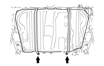
Install the 2 fuel tank bands with the 2 pins.
Set the fuel tank assembly onto the transmission jack.
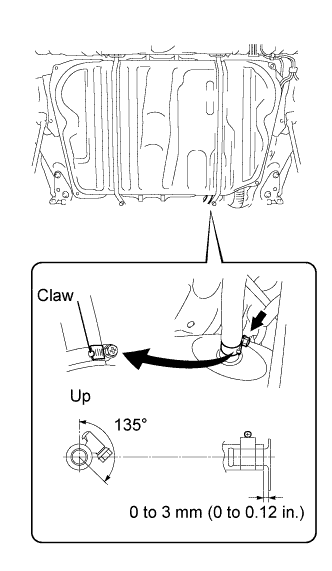
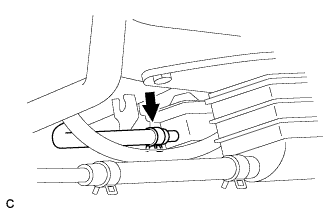
Raise the transmission jack so that the fuel tank vent hose can be connected as shown in the illustration.
NOTICE:
Slowly raise the jack not to drop the fuel tank assembly.
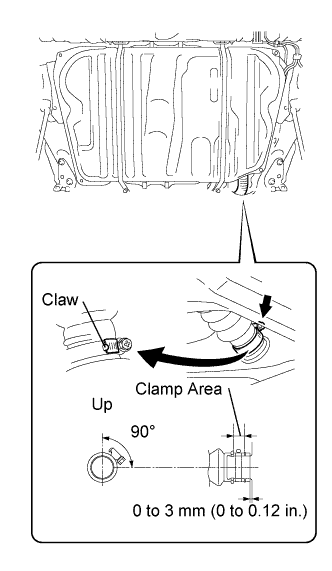
Connect the fuel tank to filler pipe hose and tighten the hose clamp as shown in the illustration.
Tighten the 2 set bolts of the fuel tank bands.
Torque:
39 N*m{
400 kgf*cm
, 29 ft.*lbf
}
Connect the fuel emission hose to the charcoal canister.
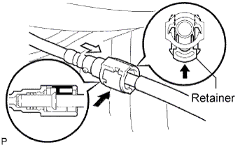
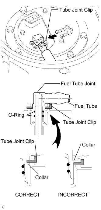
Connect the fuel pump tube.
Push the fuel connector into the pipe and push up the retainer so that the claws engage.
NOTICE:
Before connecting the tube, make sure that it is not damaged. Make sure that there is no dirt present on the connecting surfaces.
After connecting, check if the fuel tube connector and the pipe are securely connected by pulling on them.
10.
INSTALL FUEL TANK PROTECTOR LOWER CENTER
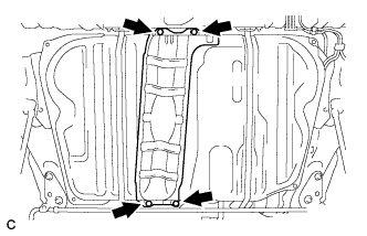
Install the 4 bolts and fuel tank protector.
Torque:
5.4 N*m{
55 kgf*cm
, 48 in.*lbf
}
11.
INSTALL REAR STABILIZER BAR NO. 1 BRACKET
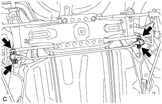
Install the 2 rear stabilizer bar No. 1 brackets with the 4 bolts.
Torque:
31 N*m{
316 kgf*cm
, 23 ft.*lbf
}
12.
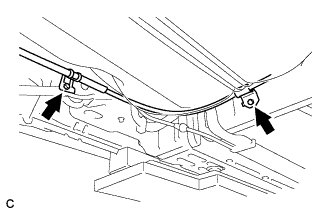
INSTALL NO. 3 PARKING BRAKE CABLE ASSEMBLY
Install the No. 3 parking brake cable assembly with the bolt and nut.
Torque:
Bolt:
6.0 N*m{
61 kgf*cm
, 53 in.*lbf
}
Nut:
8.5 N*m{
87 kgf*cm
, 75 in.*lbf
}
13.
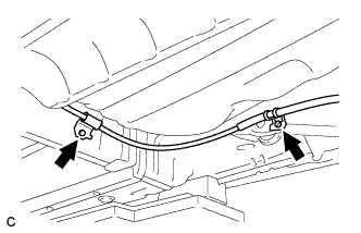
INSTALL NO. 2 PARKING BRAKE CABLE ASSEMBLY
Install the No. 2 parking brake cable assembly with the bolt and nut.