Touch Sensor Circuit
Circuit diagnosis · Vehicles built from Jun 2009
Versions by build date: Oct 2006 – May 2009 from Jun 2009
DESCRIPTION
This circuit receives a signal indicating whether a touch sensor signal is detected.The touch sensor is built into the door outside handle of the driver door and passenger door.
WIRING DIAGRAM
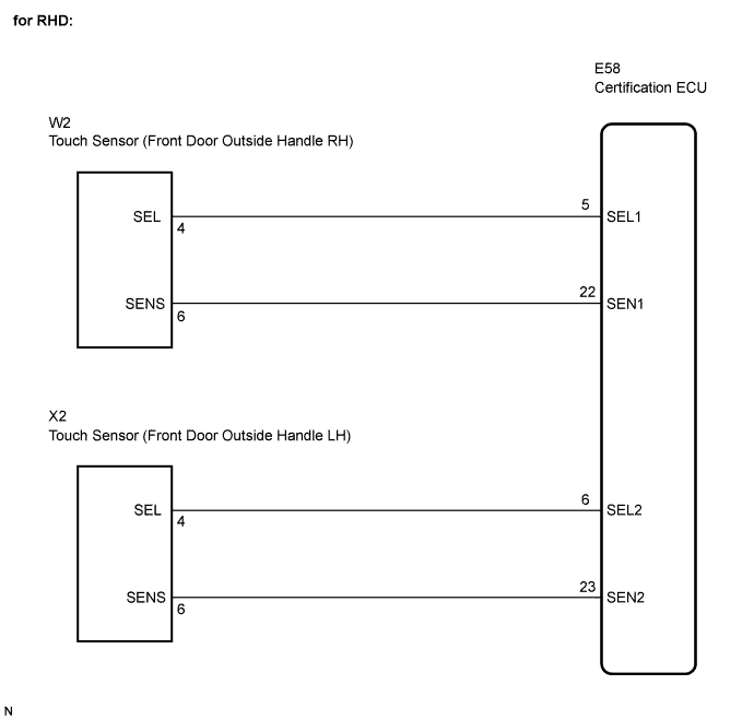

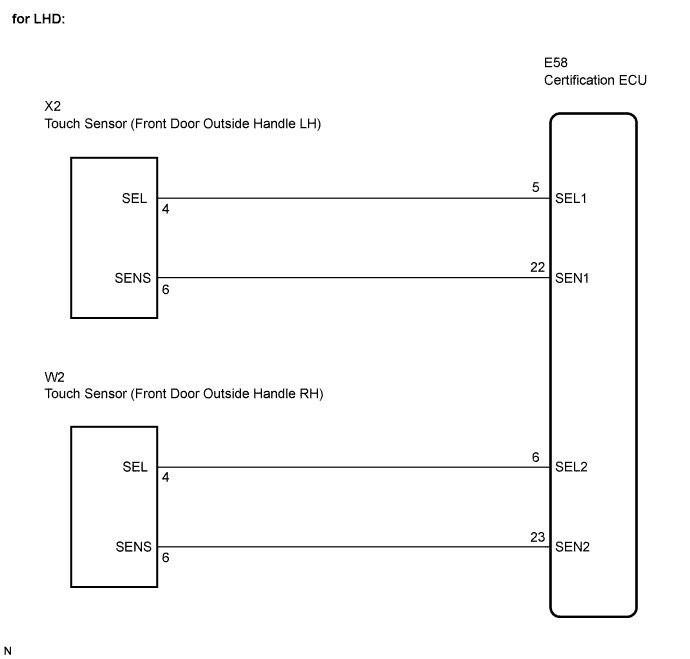
INSPECTION PROCEDURE
| 1. READ VALUE ON INTELLIGENT TESTER |

Connect the intelligent tester to the DLC3.
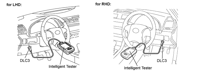
Turn the engine switch on (IG) and turn the intelligent tester main switch on.
Select D Touch Sensor in the DATA LIST and read the tester display.
Entry and Start (Certification ECU): Tester Display
Measurement Item/Range
Normal Condition
Diagnostic Note
D Touch Sensor
Status of driver side door touch sensor / ON or OFF
ON: Touch sensor is touched
OFF: Touch sensor is not touched
-
P Touch Sensor
Status of touch sensor front RH / ON or OFF
ON: Touch sensor is touched
OFF: Touch sensor is not touched
-
- OK:
- "ON" (sensor is touched) or "OFF" (sensor is not touched) appears on the tester screen.
|
|
||||

| NG | |
 |
| 2. CHECK HARNESS AND CONNECTOR (CERTIFICATION ECU - ELECTRICAL KEY OSCILLATOR) |
Disconnect the E58 ECU connector.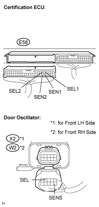
Disconnect the oscillator connectors.
Measure the resistance according to the value(s) in the table below.
- Standard resistance:
- for LHD (Front LH Side):
Tester Connection (Symbols)
Condition
Specified Condition
E58-5 (SEL1) - X2-4 (SEL)
Always
Below 1 Ω
E58-22 (SEN1) - X2-6 (SENS)
Always
Below 1 Ω
E58-5 (SEL1) - Body ground
Always
10 kΩ or higher
E58-22 (SEN1) - Body ground
Always
10 kΩ or higher
- for LHD (Front RH Side):
Tester Connection (Symbols)
Condition
Specified Condition
E58-6 (SEL2) - W2-4 (SEL)
Always
Below 1 Ω
E58-23 (SEN2) - W2-6 (SENS)
Always
Below 1 Ω
E58-6 (SEL2) - Body ground
Always
10 kΩ or higher
E58-23 (SEN2) - Body ground
Always
10 kΩ or higher
- for RHD (Front RH Side):
Tester Connection (Symbols)
Condition
Specified Condition
E58-5 (SEL1) - W2-4 (SEL)
Always
Below 1 Ω
E58-22 (SEN1) - W2-6 (SENS)
Always
Below 1 Ω
E58-5 (SEL1) - Body ground
Always
10 kΩ or higher
E58-22 (SEN1) - Body ground
Always
10 kΩ or higher
- for RHD (Front LH Side):
Tester Connection (Symbols)
Condition
Specified Condition
E58-6 (SEL2) - X2-4 (SEL)
Always
Below 1 Ω
E58-23 (SEN2) - X2-6 (SENS)
Always
Below 1 Ω
E58-6 (SEL2) - Body ground
Always
10 kΩ or higher
E58-23 (SEN2) - Body ground
Always
10 kΩ or higher
|
|
||||
| OK | |
|
| 3. CHECK AND REPLACE ELECTRICAL KEY OSCILLATOR (CHECK OPERATION OF OSCILLATOR) |
Replace the door oscillator.
Check that the entry UNLOCK function operates normally.
- OK:
- Entry UNLOCK function operates normally.
|
|
||||
| OK | |
|
| 4. INSPECT CERTIFICATION ECU |
Reconnect the ECU and the oscillator connectors.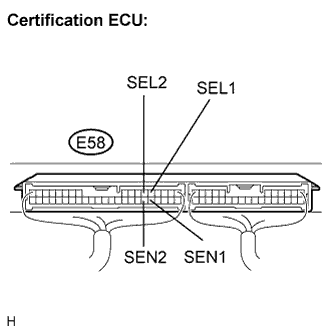
Turn the engine switch on (IG).
Measure the voltage according to the value(s) in the table below.
- Standard voltage:
Tester Connection (Symbols)
Condition
Specified Condition
E58-5 (SEL1) - Body ground
Move the key more than 5 m (16.4 ft) away from the front door LH
10 to 14 V
E58-5 (SEL1) - Body ground
Bring the key to the outside handle
Below 1 V
E58-6 (SEL2) - Body ground
Move the key more than 5 m (16.4 ft) away from the front door RH
10 to 14 V
E58-6 (SEL2) - Body ground
Bring the key to the outside handle
Below 1 V
E58-22 (SEN1) - Body ground
Front door LH outside handle is not held (Bring the electrical key to the outside handle)
10 to 14 V
E58-22 (SEN1) - Body ground
Front door LH outside handle is held
Below 1 V
E58-23 (SEN2) - Body ground
Front door RH outside handle is not held (Bring the electrical key to the outside handle)
10 to 14 V
E58-23 (SEN2) - Body ground
Front door RH outside handle is held
Below 1 V
|
|
||||
| OK | ||
 |
||
| ||