2006-2011 Camry Aurion · Service Manual BODY

REMOVAL

Removal / installation · Vehicles built Oct 2006 – May 2009

Versions by build date: Jun 2006 – Sep 2006 Oct 2006 – May 2009 from Jun 2009


1. REMOVE FRONT DOOR LOWER FRAME BRACKET GARNISH

  1. B132833
    Disengage the 2 clips and remove the front door lower frame bracket garnish.


2. REMOVE FRONT DOOR INSIDE HANDLE BEZEL PLUG

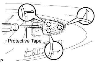
  1. B132834E01
    Using a screwdriver with the tip wrapped with protective tape, disengage the 3 claws, and remove the front door inside handle bezel plug.


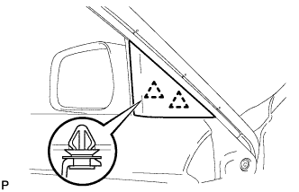
3. REMOVE ASSIST GRIP COVER

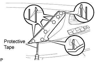
  1. B132836E01
    Using a screwdriver with the tip wrapped with protective tape, disengage the 6 claws and remove the assist grip cover.


4. REMOVE COURTESY LIGHT ASSEMBLY (w/ Courtesy Light)

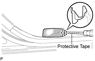
  1. B132838E01
    Using a screwdriver with the tip wrapped with protective tape, disengage the claw and remove the courtesy light assembly.

  1. Disconnect the connector.


5. REMOVE FRONT DOOR TRIM BOARD SUB-ASSEMBLY

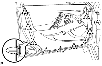
  1. B132840E01
    Remove the 3 screws and clip (A).

  1. Using a clip remover, disengage the 9 clips.

  1. B136401E01
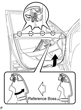
    Pull up the front door trim board in the direction indicated by the arrow.

  1. Disengage the reference bosses from the front door panel.

  1. Raise the front door trim board to disengage the 4 claws and remove the front door trim board together with the front door inner glass weatherstrip.

  1. B136403
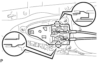
    Disengage the 2 claws and disconnect the front door inside handle sub-assembly.


6. REMOVE FRONT DOOR INNER GLASS WEATHERSTRIP

  1. B136404
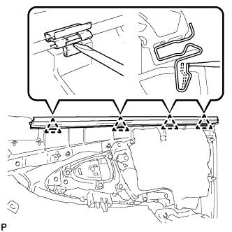
    Using a screwdriver, disengage the 4 clips as shown in the illustration and remove the front door inner glass weatherstrip from the front door trim board.

7. REMOVE OUTER REAR VIEW MIRROR GLASS (for 2GR-FE)

  1. B163654
    Adjust the mirror glass to the fully inboard and upward position.

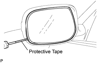
  1. B163651E01
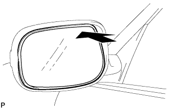
    Insert a screwdriver with the tip taped between the mirror housing and the mirror glass as shown in the illustration.

    NOTICE:
    The screwdriver should be securely wedged up against the back of the mirror glass.

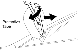
  1. B163652E01
    Twist the screwdriver to separate the mirror glass from the motor plate.


8. REMOVE OUTER MIRROR COVER (for 2GR-FE)

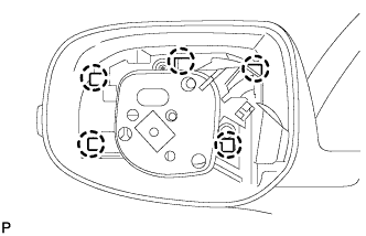
  1. B163653
    Disengage the 5 claws and remove the outer mirror cover.


9. REMOVE SIDE TURN SIGNAL LIGHT ASSEMBLY (for 2GR-FE)

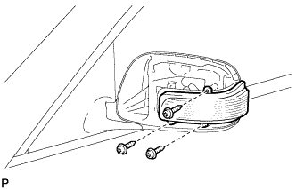
  1. E147644
    Using a "TORX" driver (T20), remove the 3 "TORX" screws.

  1. Pull out the bulb holder and remove the side turn signal light assembly.


10. REMOVE OUTER REAR VIEW MIRROR ASSEMBLY

  1. B149066
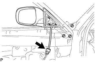
    Disconnect the connector.

  1. Remove the 3 nuts and the outer rear view mirror assembly.

← REMOVAL (Jun 2006 – Sep 2006)REMOVAL (from Jun 2009) →