REMOVAL
Removal / installation · Vehicles built Jun 2006 – Sep 2006
Versions by build date: Jun 2006 – Sep 2006 Oct 2006 – May 2009 from Jun 2009
| 1.
PRECAUTION |
 |
Be sure to read "PRECAUTION" thoroughly before servicing (Click here).
| 2.
DISCONNECT CABLE FROM NEGATIVE BATTERY TERMINAL |
|
- CAUTION:
- Wait for 90 seconds after disconnecting the cable to prevent airbag deployment.
| 3.
ALIGN FRONT WHEELS FACING STRAIGHT AHEAD |
|
| 4.
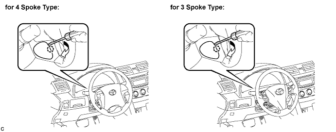
REMOVE NO. 2 LOWER STEERING WHEEL COVER
|
|
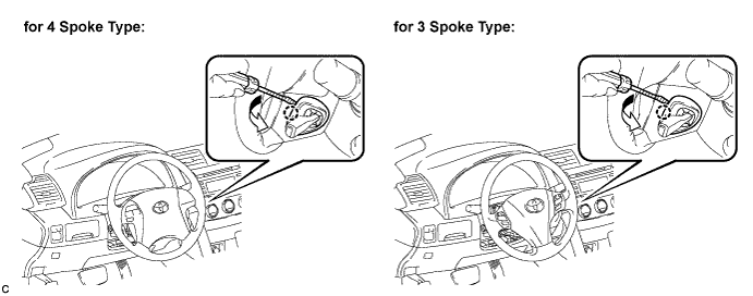
Using a screwdriver, disengage the claw and remove the No. 2 lower steering wheel cover.

- HINT:
- Tape up the screwdriver tip before use.
| 5.
REMOVE NO. 3 LOWER STEERING WHEEL COVER
|
|
Using a screwdriver, disengage the claw and remove the No. 3 lower steering wheel cover.
- HINT:
- Tape up the screwdriver tip before use.
| 6.
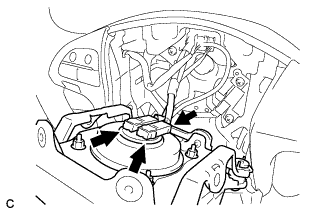
REMOVE STEERING PAD
|
|
Using a "TORX" socket (T30), loosen the 2 "TORX" screws until the groove along the screw circumference catches on the screw case.
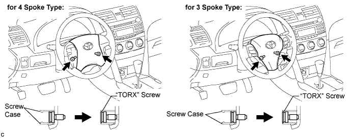
- Pull out the steering pad from the steering wheel assembly and support the steering pad with one hand.
- NOTICE:
- When removing the steering pad, do not pull the airbag wire harness.
Disconnect the horn connector from the steering pad.
Disconnect the 2 airbag connectors and remove the steering pad.
- NOTICE:
- When handling the airbag connector, take care not to damage the airbag wire harness.
| 7.
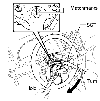
REMOVE STEERING WHEEL ASSEMBLY
|
|
Remove the steering wheel assembly set nut.
Put matchmarks on the steering wheel assembly and the steering main shaft.
Disconnect the connectors from the spiral cable.
- Using SST, remove the steering wheel assembly.
- SST
- 09950-50013
(09951-05010, 09952-05010, 09953-05020, 09954-05031)
| 8.
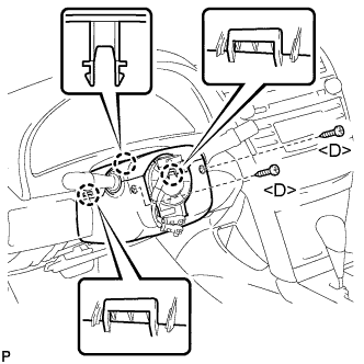
REMOVE STEERING COLUMN COVER
|
|
- Remove the 2 screws <D>.
Disengage the 2 claws and remove the lower steering column cover.
Disengage the claw and remove the upper steering column cover.
| 9.
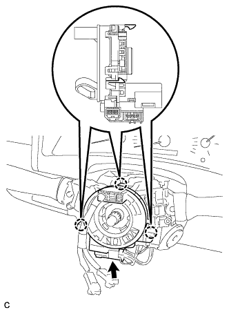
REMOVE SPIRAL CABLE WITH STEERING ANGLE SENSOR
|
|
- Disconnect the connectors from the spiral cable with steering angle sensor.
- NOTICE:
- When handling the airbag connector, take care not to damage the airbag wire harness.
Disengage the 3 claws and remove the spiral cable with steering angle sensor.
| 10.
REMOVE WINDSHIELD WIPER SWITCH ASSEMBLY
|
|
- Disconnect the 2 connectors.
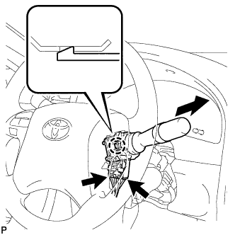
Disengage the claw and remove the windshield wiper switch assembly as shown in the illustration.
- NOTICE:
- If the claw is pushed with excessive force, it may break.
| 11.
REMOVE HEADLIGHT DIMMER SWITCH ASSEMBLY |
|
- Disconnect the connector.
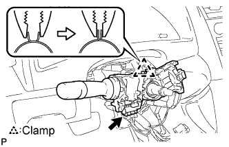
Disengage the clamp as shown in the illustration.
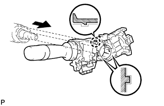
- Disengage the claw and remove the headlight dimmer switch assembly as shown in the illustration.