Power Mirrors do not Return to Memorized Position
Circuit diagnosis · Vehicles built from Oct 2006
DESCRIPTION
When the seat memory switch M1 or M2 is pressed, the power seat switch RH transmits a signal of the memorized mirror position to the outer mirror control ECU. Then, the outer mirror control ECU drives the mirror motor.WIRING DIAGRAM
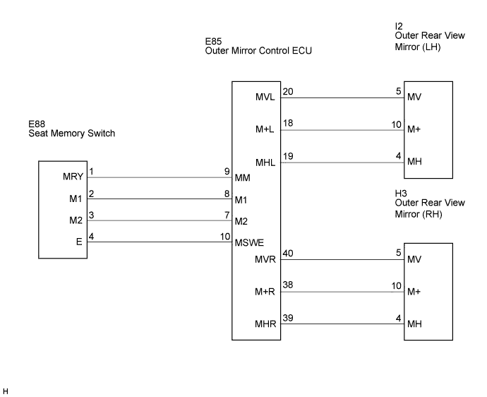

INSPECTION PROCEDURE
| 1. READ VALUE USING INTELLIGENT TESTER |

Check the Data List for proper function of the seat memory switch.
- Mirror-L/Mirror-R:
Item
Switch Position
Specified Condition
Driver Side Memory SW1
Driver side mirror position memorized in seat memory switch M1/ON (1) or OFF (2)
1: Memorized
0: Not memorized
Driver Side Memory SW2
Driver side mirror position memorized in seat memory switch M2/ON (1) or OFF (2)
|
|
||||

| OK | ||
 |
||
| ||
| 2. CHECK SEAT MEMORY SWITCH |
Remove the seat memory switch.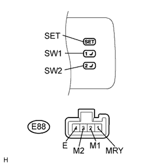
Measure the resistance according to the value(s) in the table below when the switch is operated.
- Standard resistance:
Tester Connection
Switch Condition
Specified Condition
4 (E) - 1 (MRY)
"SET" switch ON
Below 1 Ω
"SET" switch OFF
10 kΩ or higher
4 (E) - 2 (M1)
"1" switch ON
Below 1 Ω
"1" switch OFF
10 kΩ or higher
4 (E) - 3 (M2)
"2" switch ON
Below 1 Ω
"2" switch OFF
10 kΩ or higher
|
|
||||

| OK | |
 |
| 3. CHECK WIRE HARNESS (SEAT MEMORY SWITCH - OUTER MIRROR CONTROL ECU) |
Disconnect the E85 and E88 switch connectors.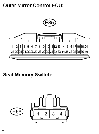
Measure the resistance according to the value(s) in the table below.
- Standard resistance:
Tester Connection
Condition
Specified Condition
E85-9 (MM) - E88-1 (MRY)
Always
Below 1 Ω
E85-8 (M1) - E88-2 (M1)
Always
E85-7 (M2) - E88-3 (M2)
Always
E85-10 (MSWE) - E88-4 (E)
Always
|
|
||||
| OK | |
|
| 4. INSPECT OUTER REAR VIEW MIRROR ASSEMBLY |
Outer rear view mirror LH:Disconnect the I2 connector.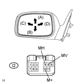
Apply battery voltage and check operation of the mirror face.
- Standard:
Measurement Condition
Mirror Operation
Battery positive (+) → I2-5 (MV)
Battery negative (-) → I2-10 (M+)
Turns upward (A)
Battery positive (+) → I2-10 (M+)
Battery negative (-) → I2-5 (MV)
Turns downward (B)
Battery positive (+) → I2-4 (MH)
Battery negative (-) → I2-10 (M+)
Turns left (C)
Battery positive (+) → I2-10 (M+)
Battery negative (-) → I2-4 (MH)
Turns right (D)
Outer rear view mirror RH:Disconnect the H3 connector.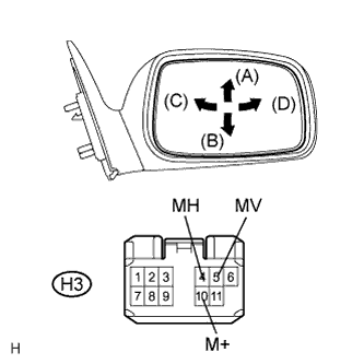
Apply battery voltage and check operation of the mirror face.
- Standard:
Measurement Condition
Mirror Operation
Battery positive (+) → H3-5 (MV)
Battery negative (-) → H3-10 (M+)
Turns upward (A)
Battery positive (+) → H3-10 (M+)
Battery negative (-) → H3-5 (MV)
Turns downward (B)
Battery positive (+) → H3-4 (MH)
Battery negative (-) → H3-10 (M+)
Turns left (C)
Battery positive (+) → H3-10 (M+)
Battery negative (-) → H3-4 (MH)
Turns right (D)
|
|
||||
| OK | ||
|
||
| ||