2006-2011 Camry Aurion · Service Manual TRANSMISSION

INSTALLATION

Removal / installation · Vehicles built from Jun 2009

Versions by build date: Jun 2006 – Sep 2006 Oct 2006 – May 2009 from Jun 2009


1. INSTALL SHIFT LOCK CONTROL UNIT

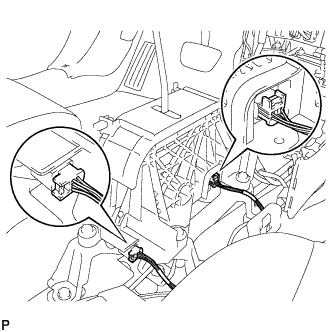
  1. C135016
    Connect the shift lock control ECU connector and transmission control switch wire connector.

  1. Install the 4 bolts and shift lever assembly.

    Torque:
    12 N*m{ 122 kgf*cm , 9 ft.*lbf }


2. INSTALL TRANSMISSION CONTROL CABLE ASSEMBLY

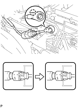
  1. C135020
    Install the transmission control cable assembly as shown in the illustration.

    HINT:
    1. Install the floor shift cable with the uneven surface facing up.
    2. Securely engage the claws of the floor shift cable.


3. INSTALL NO. 1 CONSOLE BOX INSERT FRONT

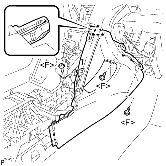
  1. B134006E01
    Engage the clip.

  1. Install the No. 1 console box insert front with the 3 screws <F>.


4. INSTALL NO. 2 CONSOLE BOX INSERT FRONT

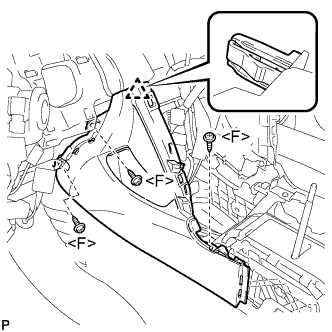
  1. B134005E01
    Engage the clip.

  1. Install the No. 2 console box insert front with the 3 screws <F>.


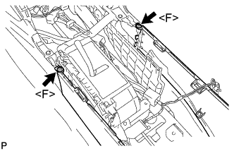
5. INSTALL CONSOLE BOX ASSEMBLY

  1. B134002E01
    Install the 2 screws <F>.

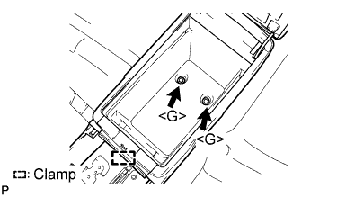
  1. B149935E03
    Install the console box assembly with the 2 bolts <G>.

  1. Engage the clamp.


6. INSTALL CONSOLE BOX CARPET

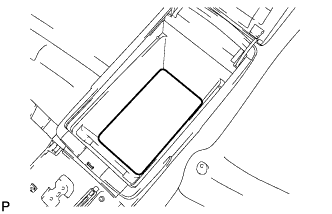
  1. B134004
    Install the console box carpet.


7. INSTALL CONSOLE BOX POCKET
  1. Install the console box pocket.


8. INSTALL UPPER CONSOLE PANEL SUB-ASSEMBLY
  1. Connect each connector.

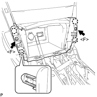
  1. B133997E01
    Engage the 4 claws.

  1. Install the upper console panel sub-assembly with the 2 screws <F>.


9. INSTALL UPPER CONSOLE REAR PANEL SUB-ASSEMBLY

HINT:
  1. for LHD: (Click here)
  2. for RHD: (Click here)


10. INSTALL POSITION INDICATOR HOUSING ASSEMBLY

HINT:
  1. for LHD: (Click here).
  2. for RHD: (Click here).


11. INSTALL NO. 2 INSTRUMENT CLUSTER FINISH PANEL GARNISH

  1. B226063
    Engage the 2 clips and install the No. 2 instrument cluster finish panel garnish.


12. INSTALL NO. 1 INSTRUMENT CLUSTER FINISH PANEL GARNISH

  1. B226064
    Engage the 2 clips and install the No. 1 instrument cluster finish panel garnish.


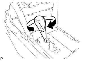
13. INSTALL SHIFT LEVER KNOB SUB-ASSEMBLY

  1. C147377
    Install the shift lever knob sub-assembly.


14. INSTALL LOWER INSTRUMENT PANEL FINISH PANEL

HINT:
  1. w/o Smart Entry and Start System: (Click here).
  2. w/ Smart Entry and Start System: (Click here).


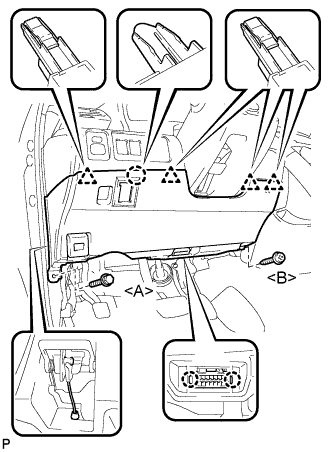
15. INSTALL LOWER NO. 1 INSTRUMENT PANEL FINISH PANEL

  1. B147264E01
    Install the air hose and connect the connector.

  1. Engage the 2 claws and the DLC3.

  1. Engage the claw and the 4 clips.

  1. Install the lower No. 1 instrument panel finish panel with the screw <B> and bolt <A>.


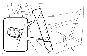
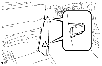
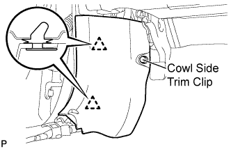
16. INSTALL COWL SIDE TRIM SUB-ASSEMBLY LH

  1. B132116E01
    Engage the 2 clips.

  1. Install the cowl side trim sub-assembly LH with the cowl side trim clip.


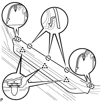
17. INSTALL FRONT DOOR SCUFF PLATE LH

  1. B132067
    Engage the 7 claws and 3 clips, then install the front door scuff plate LH.


18. CONNECT CABLE TO NEGATIVE BATTERY TERMINAL

Torque:
6.9 N*m{ 70 kgf*cm , 61 in.*lbf }


19. INSPECT SHIFT LEVER POSITION
  1. When shifting from the P to the R position with the ignition switch on (IG) and brake pedal depressed, make sure that the shift lever moves smoothly and moves correctly into position.

  1. Start the engine and make sure that the vehicle moves forward when shifting from the N to the D position and moves rearward when shifting to the R position.
    If operation cannot be done as specified, inspect the park/neutral position switch assembly and check the shift lever assembly installation condition.


20. ADJUST SHIFT LEVER POSITION
  1. Move the shift lever to the N position.

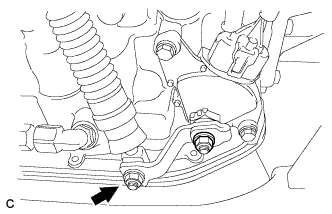
  1. C135109
    Remove the nut from the control shaft lever.

  1. Disconnect the transmission control cable assembly from the control shaft lever.

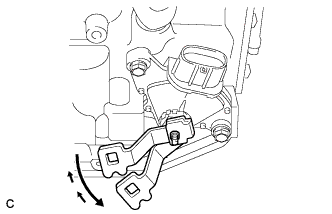
  1. C135711
    Push the control shaft lever fully downward.

  1. Return the control shaft lever 2 notches to the N position.

  1. C135734E02
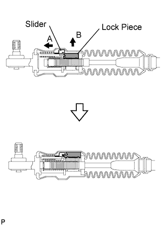
    Move the slider in the direction indicated by arrow A and pull up the lock piece in the direction indicated by arrow B.

    NOTICE:
    Do not damage the boot.

  1. C135109
    Install the transmission control cable to the control shaft lever with the nut.

    Torque:
    15 N*m{ 148 kgf*cm , 11 ft.*lbf }

    NOTICE:
    1. If the control cable end is excessively pushed up, the shift lever cannot be adjusted.
    2. When tightening the nut, confirm that the control cable is properly stretched.

  1. C138300E01
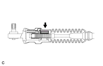
    Push in the lock piece.

    NOTICE:
    Firmly push in the lock piece until the slider lock is engaged.

    HINT:
    After pushing the lock piece make sure that the boot is not deformed.

  1. Start the engine and make sure that the vehicle moves forward when moving the shift lever from the N to the D position and moves rearward when moving it to the R position.
    If it becomes hard to move the shift lever, readjust the shift lever position.

← INSTALLATION (Oct 2006 – May 2009)COMPONENTS (from Jun 2006) →