SYSTEM DESCRIPTION
Troubleshooting · Vehicles built Jun 2006 – May 2009
Versions by build date: Jun 2006 – May 2009 from Jun 2009
| MANUAL LIGHT CONTROL SYSTEM |
The main body ECU controls this system based on the signals listed below.
Input
Output
Lights that illuminate
Light control switch TAIL signal
Taillight relay drive signal
- Taillights
- License plate lights
- Parking lights
Light control switch HEAD signal
Headlight relay drive signal
Low beam headlights
- Taillights
| AUTOMATIC LIGHT CONTROL SYSTEM |
The main body ECU controls this system based on the signals listed below.
Input
Output
Lights that illuminate
- Light control switch AUTO signal
- Automatic light control sensor signal
- Headlight relay drive signal
- Taillight relay drive signal
- Low beam headlights
- Taillights
- License plate lights
- Parking lights
- Light control switch AUTO signal
| LIGHT AUTO TURN OFF SYSTEM |
The main body ECU controls this system based on the signals listed below.
Input
Output
Lights that operate
- Combination switch signal
- Door courtesy switch signal
- Ignition switch signal
- Headlight relay OFF demand
- Taillight relay OFF demand
- High beam headlight relay OFF demand
- Front fog light relay OFF demand
- Rear fog light relay OFF demand
- Low beam headlights
- Taillights, license plate lights and parking lights
- High beam headlights
- Front fog lights
- Rear fog lights
- Combination switch signal
| ILLUMINATED ENTRY SYSTEM |
The main body ECU controls this system. The operation and condition of the illuminated entry system are described below.
Operation
Condition
Fade in
When either of the following conditions is met, the interior light and ignition key cylinder light fade in: - Any door is opened.
- Any door is unlocked when the ignition switch is off and all doors are closed.
- Ignition switch is turned from ACC position to OFF when all doors are closed.
Fade out immediately
When either of the following conditions is met, the interior light and ignition key cylinder light fade out: - The ignition switch is turned from OFF to the ACC or ON position when all doors are closed.
- All doors are locked when the ignition switch is off.
Illuminate for approximately 15 seconds, and then fade out
Any doors are closed when the ignition switch is off.
Fade out (Battery saving)
When the following conditions are met, the interior light and ignition key cylinder light fade out: - A key is not inserted in the ignition key cylinder.
- There are no changes in the condition of the doors for 20 minutes.
- Any door is opened.
| POWER DISTRIBUTOR |
General
- The power distributor is built into the engine room relay block, and uses a small mechanical relay and semiconductor relay for a compact and lightweight design.
- When a short circuit occurs between the power distributor and high beam headlight bulb, a fail-safe function operates to stop the high beam headlight relay operation.
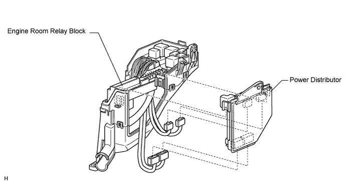

- The power distributor is built into the engine room relay block, and uses a small mechanical relay and semiconductor relay for a compact and lightweight design.
The components of the power distributor are shown below.
Component
Relay
Mechanical Relay
- Horn Relay
- A/F Relay
- Security Horn Relay
- EFI Relay
- Circuit Opening Relay
- Headlight Relay RH
- Headlight Relay LH
Semiconductor Relay
High Beam Headlight Relay
- Horn Relay
| MANUAL HEADLIGHT BEAM LEVEL CONTROL SYSTEM |
When the vehicle posture changes in accordance with the number (weight) of passengers and volume of luggage, this system enables the adjustment of the LO beam level (11-step) of the headlights manually to the appropriate level based on the position of the headlight leveling switch.
- The beam level of the headlight can be adjusted by the headlight leveling motor that is installed in the headlight assembly.
- A headlight leveling switch is provided to allow the driver to control this system.
- The beam level of the headlight can be adjusted by the headlight leveling motor that is installed in the headlight assembly.