REMOVAL
Removal / installation · Vehicles built from Jun 2009
Versions by build date: Oct 2006 – May 2009 from Jun 2009
| 1.
REMOVE FRONT DOOR SCUFF PLATE RH |
 |
- HINT:
- Use the same procedure for the RH side and the LH side (Click here).
| 2.
REMOVE COWL SIDE TRIM SUB-ASSEMBLY RH |
|
- HINT:
- Use the same procedure for the RH side and the LH side (Click here).
| 3.
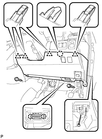
REMOVE LOWER NO. 1 INSTRUMENT PANEL FINISH PANEL
|
|
- Remove the screw and the bolt.
Disconnect the hood lock control cable assembly.
Disengage the claw and the 4 clips.
Disengage the 2 claws and remove the DLC3.
Remove the air hose, disconnect each connector, and then remove the lower No. 1 instrument panel finish panel.
| 4.
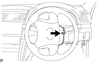
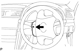
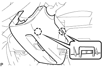
REMOVE STEERING COLUMN COVER
|
|
- Turn the steering wheel assembly to the right and remove the screw as shown in the illustration.
- Turn the steering wheel assembly to the left and remove the screw as shown in the illustration.
- Disengage the 2 claws and remove the steering column cover lower.
- Disengage the claw and remove the steering column cover upper.
| 5.
REMOVE NO. 1 INSTRUMENT PANEL SUB-ASSEMBLY
|
|
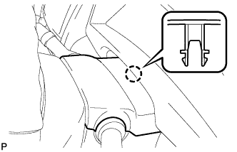
- Disengage the 3 claws and the 2 clips.
Disconnect each connector and remove the No. 1 instrument panel sub-assembly.
| 6.
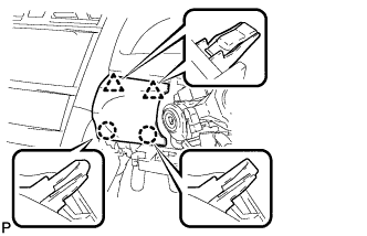
REMOVE LOWER INSTRUMENT PANEL FINISH PANEL (w/o Smart Entry and Start System)
|
|
- Disengage the 2 claws and 2 clips, and then remove the lower instrument panel finish panel.
| 7.
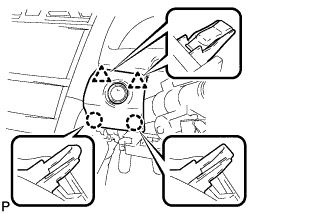
REMOVE LOWER INSTRUMENT PANEL FINISH PANEL (w/ Smart Entry and Start System)
|
|
- Disengage the 2 claws and 2 clips, and then remove the lower instrument panel finish panel.
Disconnect the connector.
| 8.
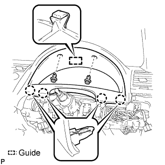
REMOVE INSTRUMENT CLUSTER FINISH PANEL SUB-ASSEMBLY
|
|
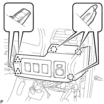
- Remove the 2 clips.
Disengage the guide and 4 claws, and then remove the instrument cluster finish panel sub-assembly.
| 9.
REMOVE COMBINATION METER ASSEMBLY
|
|
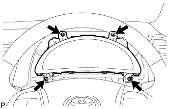
Using the tilt and telescopic functions, fully lower and extend the steering wheel.
- Remove the 4 screws.
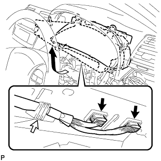
- Disconnect the 2 connectors.
Disengage the wire harness from the combination meter assembly.
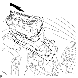
- Remove the combination meter assembly as shown in the illustration.
| 10.
REMOVE TURN SIGNAL FLASHER ASSEMBLY
|
|
- Disconnect the connector.
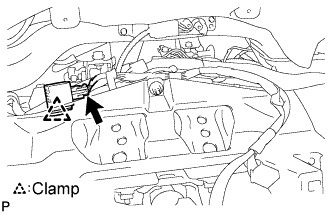
Remove the clamp and the turn signal flasher assembly.