TL19 Speaker Not Detected
Diagnostic trouble codes · Vehicles built from Oct 2006
DESCRIPTION
The Toyota Link system uses the LH rear side speaker to provide a means for voice communication from the Toyota Link Call Centre. Audible tones are also provided to indicate the system status and are broadcast via the speaker to alert the customer to certain operating conditions.Whenever the Toyota Link system is activated, the radio mute signal is also activated and the mayday ECU grounds the radio mute circuit, causing the circuit voltage to be pulled low (less than 2 V). This low voltage is detected by the radio as a mute request and when received, the audio system will mute.
Whilst the Toyota Link system is not on a call, the mute request from the cellular telephone connector will be passed through the mayday ECU to the audio system.
When a Toyota Link call is active, the mayday ECU will ignore the phone audio and transmit the mayday ECU audio to the speaker.
| Light Status |
Audible Beeps |
Description |
| All lights flash momentarily (when the engine switch is turned on (IG)) |
1 |
Confirms the system is working correctly. |
| Flashing red and green light (for 30 sec.) |
5 |
Toyota Link is in Service mode. The beeps will occur every time the engine switch is turned on (IG) or off. Press the Toyota Link button to request this mode be disabled. |
INSPECTION PROCEDURE
| 1. CHECK DTCs |

Turn the engine switch on (IG).
Select: Diagnosis / DTC List / Current DTC / Clear Current DTCs.
Select: Back / History DTC / Clear Current DTCs.
Turn the engine switch off for 1 minute, then on (IG) again.
Is DTC TL19 reset?
|
|
||||

| YES | |
 |
| 2. CHECK MAYDAY ECU TO AUDIO WIRE HARNESS FOR SHORT TO GROUND |
Disconnect the mayday ECU unit connector N46.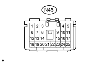

Connect a digital multimeter between terminal 22 and ground and check for continuity.
- Standard:
- Greater than 1 MΩ
Connect a digital multimeter between terminal 23 and ground and check for continuity.
- Standard:
- Greater than 1 MΩ
Is the continuity as specified?
|
|
||||
| YES | |
|
| 3. MEASURE SPEAKER RESISTANCE AT MAYDAY ECU |
Connect a digital multimeter between terminals 22 and 23.
Measure the resistance.
- OK:
- Approximately 4 Ω
|
|
||||

| NG | |
|
| 4. MEASURE SPEAKER RESISTANCE |
Disconnect the LH rear side speaker connector O12.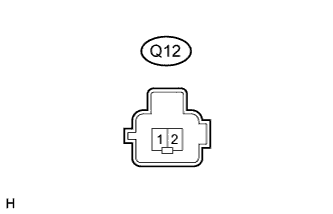
Connect a digital multimeter between speaker terminals 1 and 2.
Measure the resistance.
- OK:
- Approximately 4 Ω
|
|
||||
| OK | |
|
| 5. CHECK MAYDAY ECU WIRE HARNESS |
Disconnect the mayday ECU connectors A and B.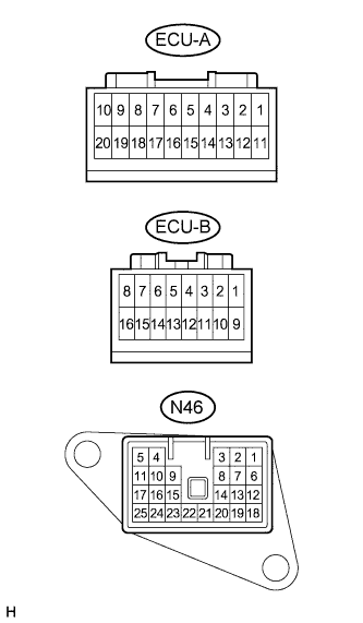
Check for continuity between the mayday ECU unit connector N46 and connectors A and B.
- OK:
- Less than 1 Ω
|
|
||||
| OK | |
|
| 6. CHECK MAYDAY ECU CONNECTORS |
Are the mayday ECU connectors tight?
|
|
||||
| YES | ||
 |
||
| ||