OPERATION CHECK
Troubleshooting · Vehicles built Oct 2006 – May 2009
Versions by build date: Oct 2006 – May 2009 from Jun 2009
| SELF-CHECK FUNCTION INSPECTION |
  |
Turn the engine switch on (IG).
- HINT:
- Wait 2 seconds after turning the engine switch on (IG).
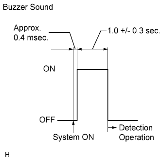
When the clearance sonar system is turned on, check that the following occurs: 1) after 0.4 milliseconds, the buzzer sounds for approximately 1 +/- 0.3 seconds, and 2) the system starts the obstacle detection operation.
- HINT:
- If a sensor has an open circuit or a sensor's detection operation malfunctions because it is wet or frozen, a malfunction display is shown on the multi-information display, and the buzzer sounds.
- When the sensor condition returns to normal, the system ends normal clearance sonar mode.
- If the engine switch is turned on (IG) after the clearance sonar main switch is turned on, the buzzer does not sound.
- If a sensor has an open circuit or a sensor's detection operation malfunctions because it is wet or frozen, a malfunction display is shown on the multi-information display, and the buzzer sounds.
| MALFUNCTION DISPLAY (MULTI-INFORMATION DISPLAY) |
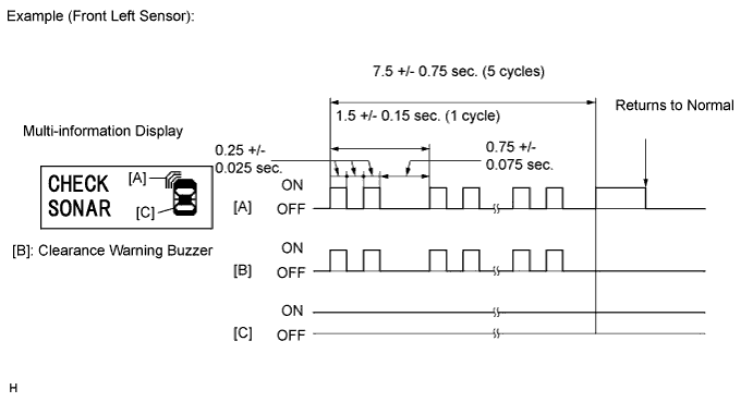
Ultrasonic sensor open circuit
If there is an open circuit between the ultrasonic sensor and the clearance warning ECU or if a sensor is malfunctioning, the malfunction is displayed as shown in the illustration.
- HINT:
- The example shows an open circuit in the ultrasonic sensor (front left sensor).
- If a sensor has an open circuit, a warning message will be displayed. In such a case, perform inspection according to the Problem Symptoms Table.
- The example shows an open circuit in the ultrasonic sensor (front left sensor).
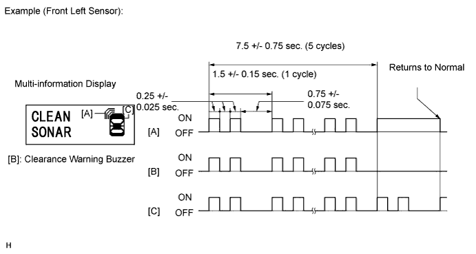
Ultrasonic sensor frozen
If a sensor is covered with foreign matter, such as mud or snow, the affected sensor is displayed as shown in the illustration.
- HINT:
- The example shows that the ultrasonic sensor (front left sensor) is covered with foreign matter.
- If a message indicating the necessity of cleaning a sonar sensor is displayed, removing the foreign matter from the sensor will return the sensor to normal.
- The example shows that the ultrasonic sensor (front left sensor) is covered with foreign matter.
| DETECTION RANGE MEASUREMENT AND DISPLAY INSPECTION |
Detection range measurement
- NOTICE:
- Make sure that the parking brake is firmly applied to prevent the vehicle from moving.
Turn the engine switch on (IG).
Move the shift lever to the reverse position to check the ultrasonic sensors (rear sensors).
Turn the clearance sonar main switch on.
Move a φ 60 mm (2.36 in.) pole near each sensor to measure its detection range.
Measure the clearance sonar's detection range.
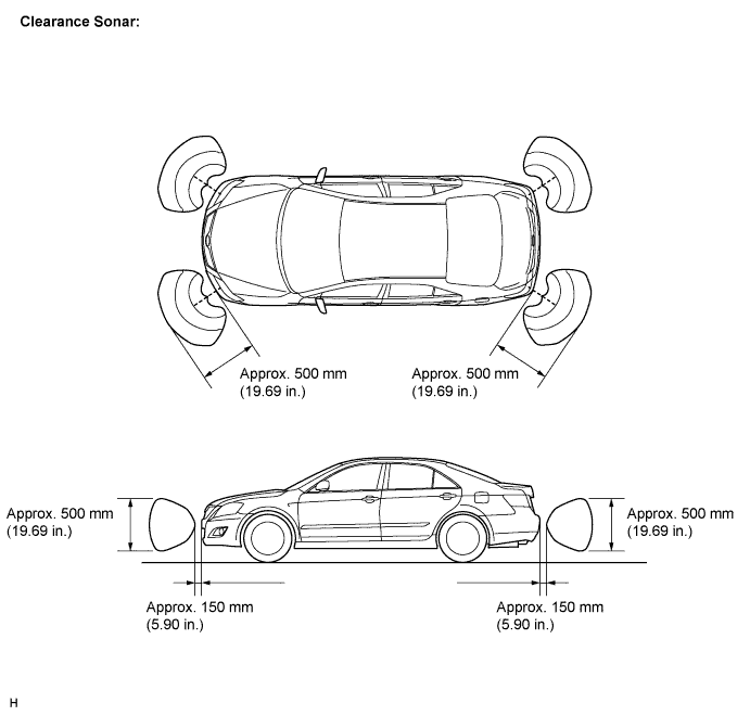
- NOTICE:
- These detection ranges are applicable when positioning the φ 60 mm (2.36 in.) pole parallel or perpendicular to the ground. The ranges vary depending on the measuring method and type of obstacle (such as walls).
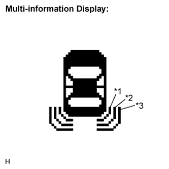
When the ultrasonic sensors (front clearance sonar) have detected an obstacle, check the display and buzzer sound.
Operation condition: Engine Switch
Clearance Sonar Main Switch
Shift Lever Position
Vehicle Speed
ON (IG)
ON
In any position except P
10 km/h (6 mph) or less
Check the buzzer sound according to the waveform shown in the illustration.
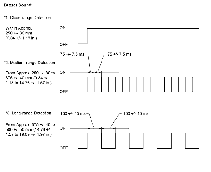
- Standard:
Detection Range
Condition
*1
Close-range detection
Within approx. 250 +/- 30 mm (9.84 +/- 1.18 in.)
Buzzer: Sounds continuously
Number of bars displayed: 1 (Blinking)
*2
Medium-range detection
From approx. 250 +/- 30 to 375 +/- 40 mm (9.84 +/- 1.18 to 14.76 +/- 1.57 in.)
Buzzer: Sounds intermittently (ON: 75 ms / OFF: 75 ms)
Number of bars displayed: 2 (Illuminated)
*3
Long-range detection
From approx. 375 +/- 40 to 500 +/- 50 mm (14.76 +/- 1.57 to 19.69 +/- 1.97 in.)
Buzzer: Sounds intermittently (ON: 150 ms / OFF: 150 ms)
Number of bars displayed: 3 (Illuminated)
- HINT:
- Ultrasonic waves are used to measure the detection range; however, the detection range may vary depending on the ambient temperature.
- Refer to the illustration of the display below.
- Ultrasonic waves are used to measure the detection range; however, the detection range may vary depending on the ambient temperature.
Check the display according to the illustration on the left while the buzzer is sounding.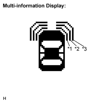
When the ultrasonic sensors (rear clearance sonar) have detected an obstacle, check the display and buzzer sound.
Operation condition: Engine Switch
Clearance Sonar Main Switch
Shift Lever Position
Vehicle Speed
ON (IG)
ON
Reverse Position
10 km/h (6 mph) or less
Check the buzzer sound according to the waveform shown in the illustration.
- Standard:
Detection Range
Condition
*1
Close-range detection
Within approx. 250 +/- 30 mm (9.84 +/- 1.18 in.)
Buzzer: Sounds continuously
Number of bars displayed: 1 (Blinking)
*2
Medium-range detection
From approx. 250 +/- 30 to 375 +/- 40 mm (9.84 +/- 1.18 to 14.76 +/- 1.57 in.)
Buzzer: Sounds intermittently (ON: 75 ms / OFF: 75 ms)
Number of bars displayed: 2 (Illuminated)
*3
Long-range detection
From approx. 375 +/- 40 to 500 +/- 50 mm (14.76 +/- 1.57 to 19.69 +/- 1.97 in.)
Buzzer: Sounds intermittently (ON: 150 ms / OFF: 150 ms)
Number of bars displayed: 3 (Illuminated)
- HINT:
- Ultrasonic waves are used to measure the detection range; however, the detection range may vary depending on the ambient temperature.
- Refer to the illustration of the display below.
- Ultrasonic waves are used to measure the detection range; however, the detection range may vary depending on the ambient temperature.
Check the display according to the illustration on the left while the buzzer is sounding.