1.
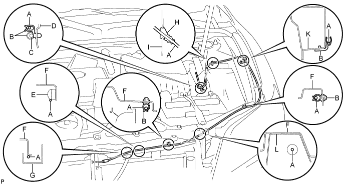
INSTALL HOOD LOCK CONTROL CABLE ASSEMBLY (for LHD)
Pass the hood lock control cable assembly into the engine compartment.
Area
Part Name
Area
Part Name
A
Hood lock control cable
G
Hood lock protector
B
Clamp
H
Grommet
C
Wire harness
I
Side member outer
D
Pillar
J
Radiator
E
Nut
K
Front fender apron
F
Radiator support upper
L
Brace
Pass the cable through the upper radiator support.
Connect the clamps as shown in the illustration.
2.
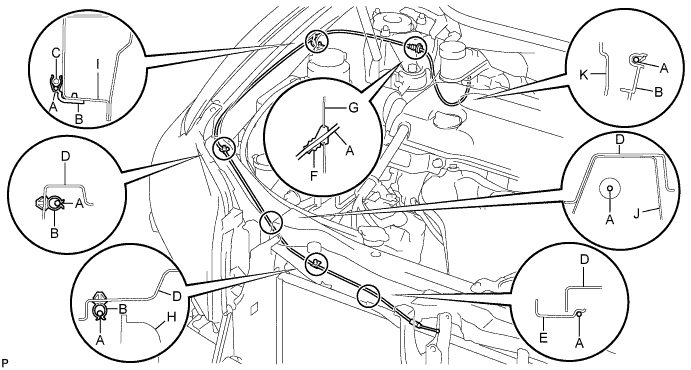
INSTALL HOOD LOCK CONTROL CABLE ASSEMBLY (for RHD)
Pass the hood lock control cable assembly into the engine compartment.
Area
Part Name
Area
Part Name
A
Hood lock control cable
G
Side member outer
B
Clamp
H
Radiator
C
Washer hose
I
Front fender apron
D
Radiator support upper
J
Brace
E
Hood lock protector
K
Pillar
F
Grommet
-
-
Pass the cable through the upper radiator support.
Connect the clamps as shown in the illustration.
3.
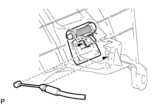
INSTALL HOOD LOCK CONTROL LEVER SUB-ASSEMBLY (for LHD)
Install the hood lock control lever and connect the hood lock control cable.
4.
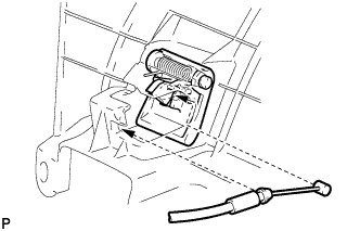
INSTALL HOOD LOCK CONTROL LEVER SUB-ASSEMBLY (for RHD)
Install the hood lock control lever and connect the hood lock control cable.
5.
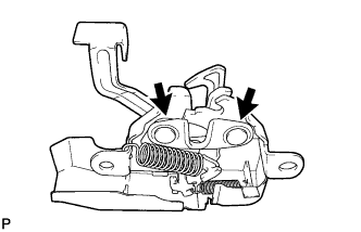
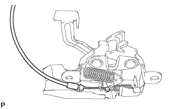
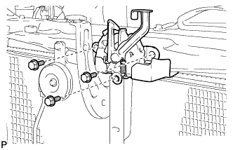
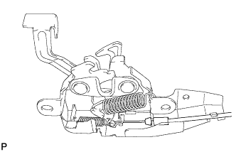
INSTALL HOOD LOCK ASSEMBLY (for LHD)
Apply MP grease to the sliding areas of the lock.
Connect the hood lock control cable.
Install the hood lock assembly with the 3 bolts.
Torque:
7.5 N*m{
77 kgf*cm
, 66 in.*lbf
}
6.
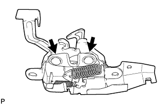
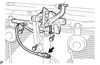
INSTALL HOOD LOCK ASSEMBLY (for RHD)
Apply MP grease to the sliding areas of the lock.
Connect the hood lock control cable.
Install the hood lock assembly with the 3 bolts.
Torque:
7.5 N*m{
77 kgf*cm
, 66 in.*lbf
}
Connect the connector.
7.
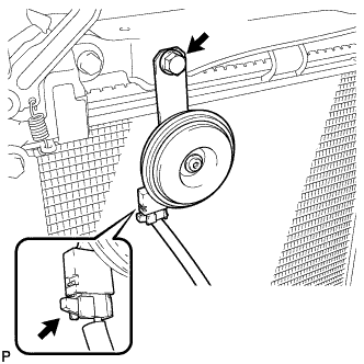
INSTALL HIGH PITCHED HORN ASSEMBLY (for LHD)
Install the high pitched horn assembly with the bolt.
Torque:
20 N*m{
204 kgf*cm
, 15 ft.*lbf
}
Connect the connector.
8.
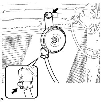
INSTALL LOW PITCHED HORN ASSEMBLY (for RHD)
Install the low pitched horn assembly with the bolt.
Torque:
20 N*m{
204 kgf*cm
, 15 ft.*lbf
}
Connect the connector.
9.
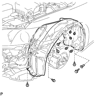
INSTALL FRONT FENDER LINER (w/o Front Fender Mudguard)
Install the front fender liner with a new grommet and 5 screws.
Install the bolt and 5 clips.
10.
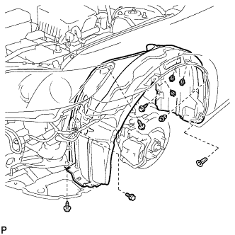
INSTALL FRONT FENDER LINER (w/ Front Fender Mudguard)
Install the front fender liner with a new grommet and 3 screws.
Install the bolt and 4 clips.
11.
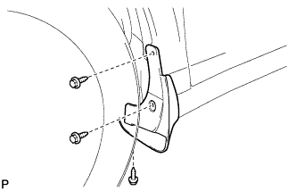
INSTALL FRONT FENDER MUDGUARD SUB-ASSEMBLY (w/ Front Fender Mudguard)
Install the front fender mudguard sub-assembly with the 3 screws.
12.
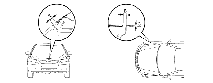
INSPECT HOOD SUB-ASSEMBLY
Check that the clearance measurements of areas A through C are within each standard range.
Standard clearance:
Area
Measurement
A
4.5 to 7.5 mm (0.177 to 0.295 in.)
B
2.0 to 5.0 mm (0.079 to 0.197 in.)
C
-1.4 to 1.6 mm (-0.055 to 0.063 in.)
13.
ADJUST HOOD SUB-ASSEMBLY
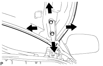
Horizontally and vertically adjust the hood.
Loosen the 4 hinge bolts of the hood.
Adjust the clearance between the hood and front fender by moving the hood.
Tighten the 4 hinge bolts after the adjustment.
Torque:
13 N*m{
133 kgf*cm
, 10 ft.*lbf
}
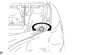
Adjust the height of the front end of the hood using the cushion rubber.
Adjust the cushion rubber so that the height of the hood and fender are aligned.
HINT:
Raise or lower the front end of the hood by turning the cushion rubber.
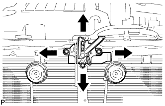
Adjust the hood lock.
Loosen the 3 bolts.
Tighten the bolts after the adjustment.
Torque:
7.5 N*m{
77 kgf*cm
, 66 in.*lbf
}
Check that the striker can engage with the hood lock smoothly.
14.
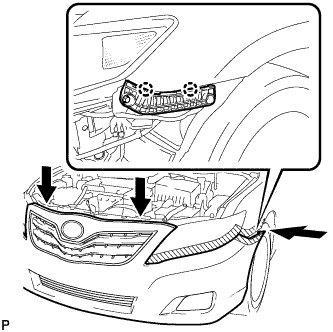
INSTALL FRONT BUMPER ASSEMBLY
w/ Fog Light:
Connect each connector.
Engage the 2 claws.
HINT:
Use the same procedure for the RH side and LH side.
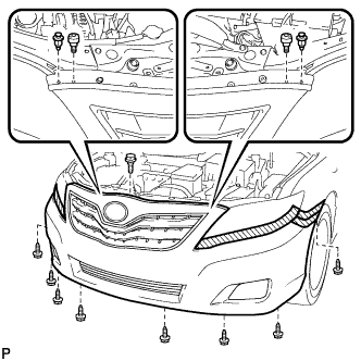
Install the front bumper assembly with the 8 screws, 2 clips, 2 radiator grille protectors and bolt.
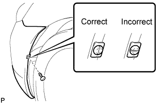
Install the pin hold clip.
NOTICE:
Insert the pin hold clip with the slot aligned vertically. Do not rotate the clip after inserting it. After installation, confirm that the slot is vertically oriented.
HINT:
Use the same procedure for the RH side and LH side.
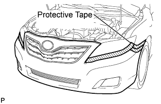
Remove the applied protective tape from the front bumper assembly.
15.
INSTALL FRONT WHEEL
Torque:
103 N*m{
1,050 kgf*cm
, 76 ft.*lbf
}
16.
VEHICLE PREPARATION FOR FOG LIGHT AIM ADJUSTMENT
Prepare the vehicle:
Ensure that there is no damage or deformation to the body around the fog lights.
Fill the fuel tank.
Make sure that the oil is filled to the specified level.
Make sure that the engine coolant is filled to the specified level.
Inflate the tires to the appropriate pressure.
Unload the trunk and vehicle, ensuring that the spare tire, tools, and jack are in their original positions.
Sit a person of average weight (75 kg, 165 lb) in the driver's seat.
Vehicles with height adjustable suspension should set the vehicle height to the lowest setting prior to adjusting the fog light aim.
17.
PREPARATION FOR FOG LIGHT AIMING
Prepare the vehicle:
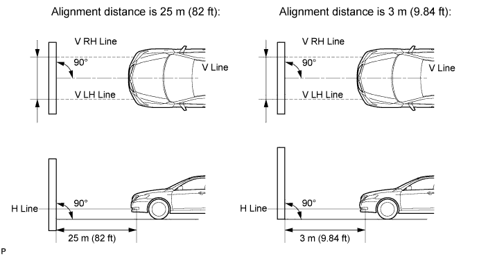
Place the vehicle in a location that is dark enough to clearly observe the cutoff line. The cutoff line is a distinct line, below which light from the fog lights can be observed and above which it cannot.
Place the vehicle at a 90° angle to the wall.
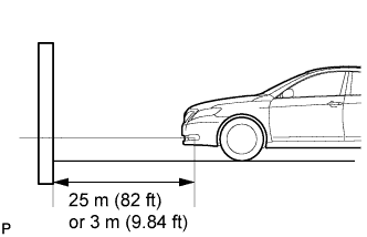
Create a 25 m (82 ft) distance between the vehicle (fog light bulb center) and the wall.
Make sure that the vehicle is on a level surface.
Bounce the vehicle up and down to settle the suspension.
NOTICE:
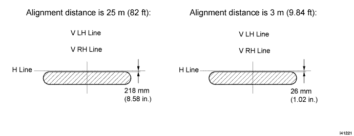
A distance of 25 m (82 ft) between the vehicle (fog light bulb center) and the wall is necessary for proper aim adjustment. If sufficient space is not available, secure a distance of exactly 3 m (9.84 ft) to allow for checking and adjustment of fog light aim. (The size of the target zone will change with the distance, so follow the instructions in the illustration.)
Prepare a piece of thick white paper (approximately 2 m (6.6 ft) (height) x 4 m (13.1 ft) (width)) to use as a screen.
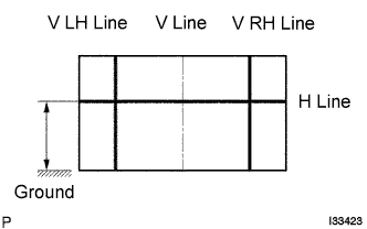
Draw a vertical line down the center of the screen (V line).
Set the screen as shown in the illustration.
HINT:
Stand the screen perpendicular to the ground.
Align the V line on the screen with the center of the vehicle.
Draw base lines (H, V LH, and V RH lines) on the screen as shown in the illustration.
HINT:
Mark the fog light bulb center marks on the screen. If the center mark cannot be observed on the fog light, use the center of the fog light bulb or the manufacturer's name marked on the fog light as the center mark.
H Line (Fog light height): Draw a horizontal line across the screen so that it passes through the center marks. The H line should be at the same height as the fog light bulb center marks of the fog lights.
V LH Line, V RH Line (Center mark position of left-hand (LH) and right-hand (RH) fog lights): Draw two vertical lines so that they intersect the H line at each center mark.
18.
FOG LIGHT AIMING INSPECTION
Cover the fog light or disconnect the connector of the fog light on the opposite side to prevent light from the fog light that is not being inspected from affecting the fog light aiming inspection.
NOTICE:
Do not keep the fog light covered for more than 3 minutes. The fog light lens is made of synthetic resin, which may melt or be damaged due to excessive heat.
Start the engine.
Turn on the fog light and check if the cut off line falls within the specified area in the following illustration.
19.
FOG LIGHT AIMING ADJUSTMENT
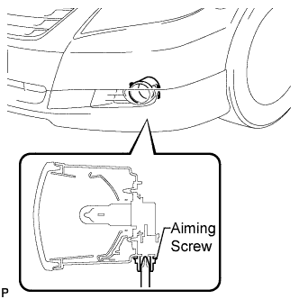
Adjust the aim vertically: Adjust the aim of each fog light to the specified range by turning each aiming screw with a screwdriver.
NOTICE:
The final turn of the aiming screw should be made in the clockwise direction. If the screw is tightened excessively, loosen it and then retighten it, so that the final turn of the screw is in the clockwise direction.
HINT:
If it is not possible to correctly adjust fog light aim, check bulb, fog light unit, and fog light unit reflector installation.