REMOVAL
Removal / installation · Vehicles built Jun 2006 – Sep 2006
| 1. REMOVE FRONT WHEEL |
| 2. REMOVE FRONT BUMPER ASSEMBLY (w/o Fog Light) |

Put protective tape around the front bumper assembly.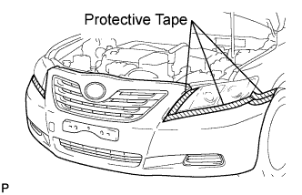

Using a screwdriver, turn the pin 90 degrees and remove the pin hold clip.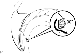
- HINT:
- Use the same procedure for the RH side and LH side.
Remove the 8 screws, 2 clips, 2 radiator grille protectors and bolt.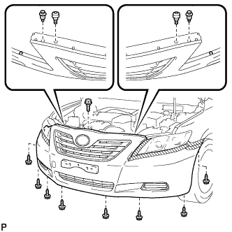
Disengage the 2 claws and disconnect the front bumper assembly as shown in the illustration.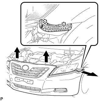
- HINT:
- Use the same procedure for the RH side and LH side.
Remove the front bumper assembly.
| 3. REMOVE FRONT BUMPER ASSEMBLY (w/ Fog Light) |
Put protective tape around the front bumper assembly.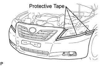
Using a screwdriver, turn the pin 90 degrees and remove the pin hold clip.
- HINT:
- Use the same procedure for the RH side and LH side.
Remove the 8 screws, 2 clips, 2 radiator grille protectors and bolt.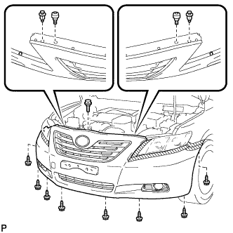
Disengage the 2 claws and disconnect the front bumper assembly as shown in the illustration.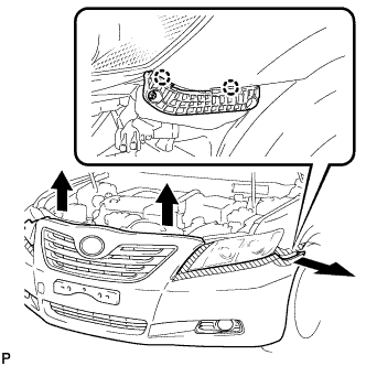
- HINT:
- Use the same procedure for the RH side and LH side.
Disconnect each connector, and then remove the front bumper assembly.
| 4. REMOVE FRONT FENDER LINER (w/o Front Fender Mudguard) |
Remove the 5 clips and bolt.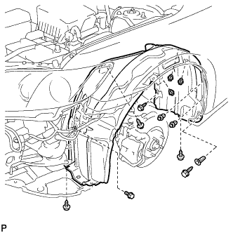
Remove the 5 screws, grommet and the front fender liner.
- HINT:
- The grommet will break when it is removed. Replace the old grommet with a new one.
| 5. REMOVE FRONT FENDER MUDGUARD SUB-ASSEMBLY (w/ Front Fender Mudguard) |
Remove the 3 screws and front fender mudguard sub-assembly.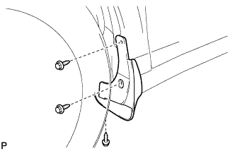
| 6. REMOVE FRONT FENDER LINER (w/ Front Fender Mudguard) |
Remove the 4 clips and bolt.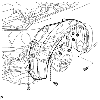
Remove the 3 screws, grommet and the front fender liner.
- HINT:
- The grommet will break when it is removed. Replace the old grommet with a new one.
| 7. REMOVE HIGH PITCHED HORN ASSEMBLY (for LHD) |
Disconnect the connector.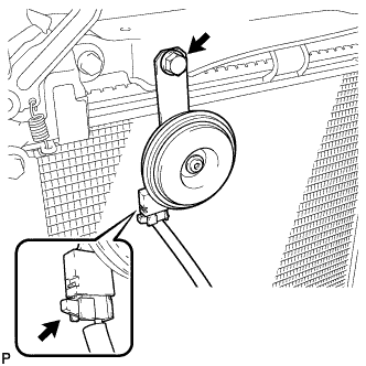
Remove the bolt and the high pitched horn assembly.
| 8. REMOVE LOW PITCHED HORN ASSEMBLY (for RHD) |
Disconnect the connector.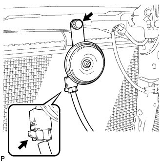
Remove the bolt and the low pitched horn assembly.
| 9. REMOVE HOOD LOCK ASSEMBLY (for LHD) |
Remove the 3 bolts.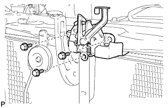
Disconnect the hood lock control cable.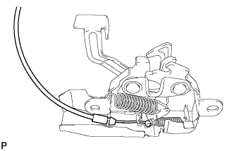
Remove the hood lock assembly.
| 10. REMOVE HOOD LOCK ASSEMBLY (for RHD) |
Disconnect the connector.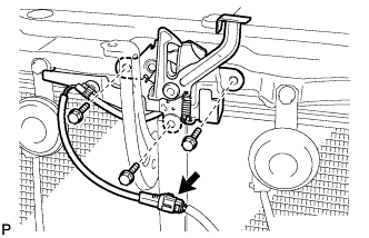
Remove the 3 bolts.
Disconnect the hood lock control cable.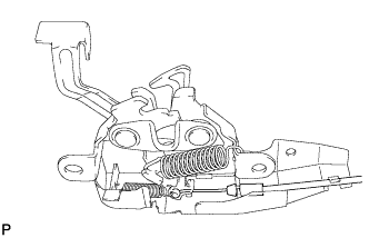
Remove the hood lock assembly.
| 11. REMOVE HOOD LOCK CONTROL LEVER SUB-ASSEMBLY (for LHD) |
Disconnect the hood lock control cable and remove the hood lock control lever.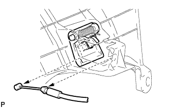
| 12. REMOVE HOOD LOCK CONTROL LEVER SUB-ASSEMBLY (for RHD) |
Disconnect the hood lock control cable and remove the hood lock control lever.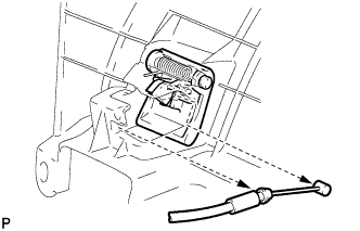
| 13. REMOVE HOOD LOCK CONTROL CABLE ASSEMBLY (for LHD) |
Using a screwdriver, disconnect the clamps shown in the illustration.
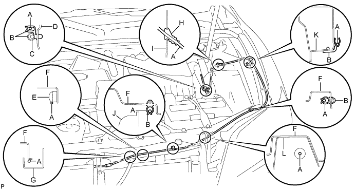
Area
Part Name
Area
Part Name
A
Hood lock control cable
G
Hood lock protector
B
Clamp
H
Grommet
C
Wire harness
I
Side member outer
D
Pillar
J
Radiator
E
Nut
K
Front fender apron
F
Radiator support upper
L
Brace
- HINT:
- Tape the screwdriver tip before use.
Pull the cable from the engine compartment and remove it.
| 14. REMOVE HOOD LOCK CONTROL CABLE ASSEMBLY (for RHD) |
Using a screwdriver, disconnect the clamps shown in the illustration.
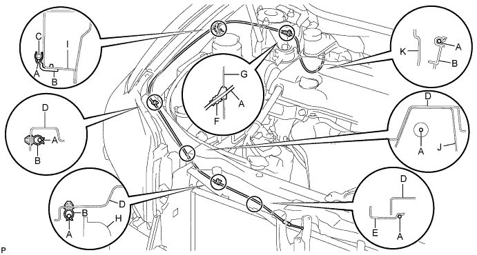
Area
Part Name
Area
Part Name
A
Hood lock control cable
G
Side member outer
B
Clamp
H
Radiator
C
Washer hose
I
Front fender apron
D
Radiator support upper
J
Brace
E
Hood lock protector
K
Pillar
F
Grommet
-
-
- HINT:
- Tape the screwdriver tip before use.
Pull the cable from the engine compartment and remove it.