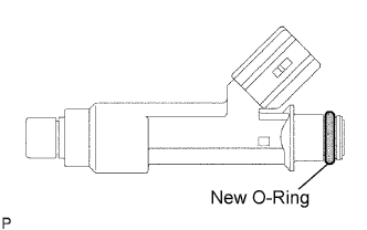
Apply a light coat of gasoline or spindle oil to new O-rings, then install one onto each fuel injector.
Apply a light coat of gasoline or spindle oil to the part of the fuel delivery pipe which comes into contact with the O-ring of the fuel injector.
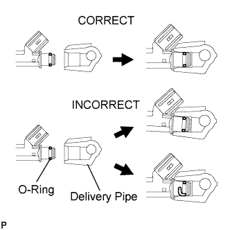
Apply a light coat of gasoline or spindle oil to the O-ring again. Install the fuel injectors onto the fuel delivery pipe while turning them left and right.
NOTICE:
Make sure that the O-ring is not cracked or jammed before installing the injector.
Check that the fuel injector rotates smoothly. If the fuel injector does not rotate, replace the O-ring.
2.
INSTALL FUEL DELIVERY PIPE WITH INJECTOR
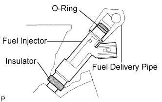
Install 4 new insulators into the cylinder head.
Install the 2 delivery pipe spacers onto the cylinder head.
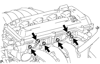
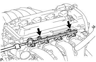
Install the fuel delivery pipe together with the 4 fuel injectors, then temporarily tighten the 2 bolts.
NOTICE:
Be careful not to drop the fuel injectors when installing the fuel delivery pipe.
Check that the fuel injector rotates smoothly. If the fuel injector does not rotate smoothly, replace the O-ring.
Tighten the 2 bolts to the specified torque.
Torque:
20 N*m{
204 kgf*cm
, 15 ft.*lbf
}
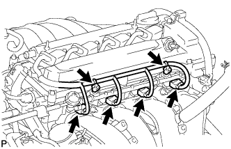
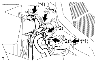
Connect the 4 fuel injector connectors.
Install the 2 wire harness clamps.
3.
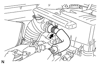
INSTALL NO. 2 VENTILATION HOSE
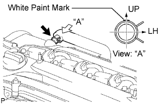
Connect the ventilation hose to the ventilation valve.
NOTICE:
Make sure that the paint mark and hose clamp are positioned as shown in the illustration after connecting the hose.
4.
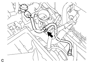
CONNECT FUEL TUBE SUB-ASSEMBLY
Install the fuel tube to the fuel hose clamp.
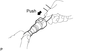
Push the fuel tube connector until it makes a "click" sound.
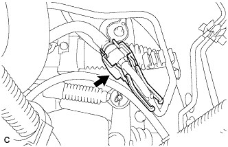
Install the No. 1 fuel pipe clamp.
5.
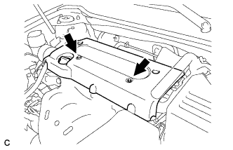
INSTALL AIR CLEANER CAP SUB-ASSEMBLY
Install the air cleaner filter element onto the air cleaner case.
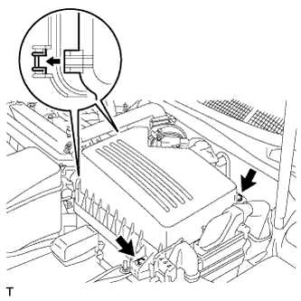
Insert the hinges. Install the air cleaner cap sub-assembly with the 2 bolts.
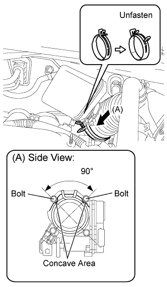
Connect the No. 1 air cleaner hose to the throttle body and unfasten the No. 1 air cleaner hose clamp.
NOTICE:
Match each concave area concavity of the air cleaner hose with the bolt of the throttle body.
Make sure that the hose clamp is at the correct angle.
Connect the No. 2 ventilation hose to the air cleaner hose.