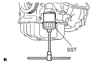
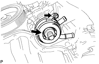
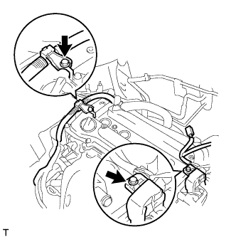
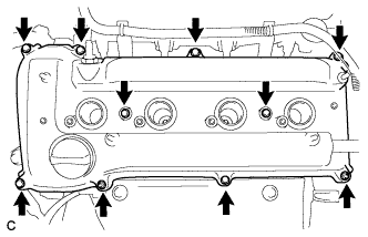
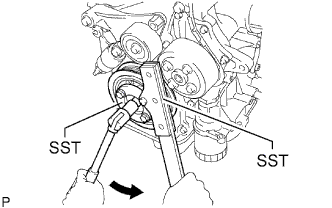
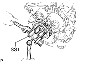
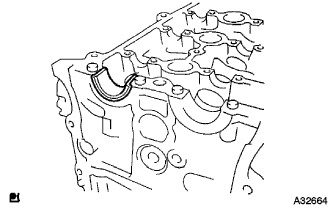
If necessary, remove the pulley and pulley bolt using SST.
13.
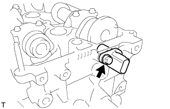
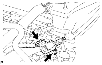
REMOVE CAMSHAFT TIMING OIL CONTROL VALVE ASSEMBLY
Disconnect the camshaft timing oil control valve assembly connector.
Remove the bolt and camshaft timing oil control valve assembly.
14.
REMOVE NO. 1 CHAIN TENSIONER ASSEMBLY
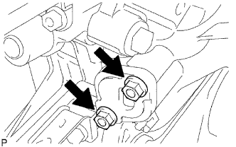
Remove the 2 nuts, tensioner and gasket.
NOTICE:
Do not turn the crankshaft without the chain tensioner.
15.
REMOVE WATER PUMP PULLEY
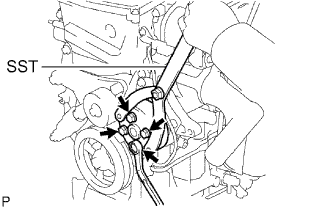
Using SST, remove the 4 bolts and water pump pulley.
SST
09960-10010
(09962-01000, 09963-00700)
16.
REMOVE WATER PUMP ASSEMBLY
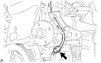
Remove the clamp of the crankshaft position sensor from the water pump.
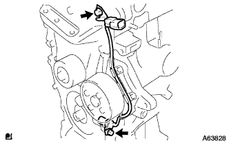
Disconnect the wire of the crankshaft position sensor from the clamp bracket.
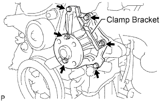
Remove the 4 bolts, 2 nuts and clamp bracket.
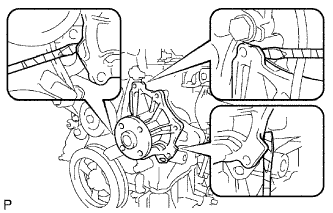
Using a screwdriver, pry between the water pump and cylinder block, and then remove the water pump.
HINT:
Tape the screwdriver tip before use.
NOTICE:
Be careful not to damage the contact surfaces of the water pump and cylinder block.
17.
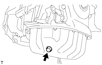
REMOVE OIL PAN DRAIN PLUG
Remove the oil pan drain plug and gasket.
18.
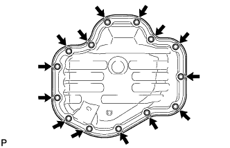
REMOVE OIL PAN SUB-ASSEMBLY
Remove the 12 bolts and 2 nuts.
Insert the blade of an oil pan seal cutter between the crankcase and oil pan. Cut through the sealer and remove the oil pan.
NOTICE:
Be careful not to damage the contact surfaces of the crankcase, chain cover and oil pan.
19.
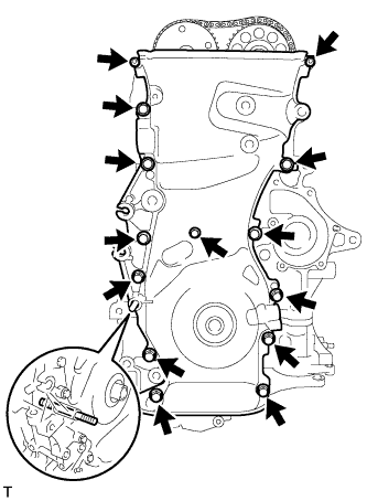
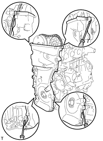
REMOVE TIMING CHAIN COVER SUB-ASSEMBLY
Using a E10 "torx" socket, remove the stud bolt for the drive belt tensioner from the cylinder block.
Remove the 12 bolts and 2 nuts.
Remove the timing chain cover by prying between the timing chain cover and cylinder head or cylinder block with a screwdriver.
NOTICE:
Be careful not to damage the contact surfaces of the timing chain cover, cylinder block and cylinder head.
HINT:
Tape the screwdriver tip before use.
20.
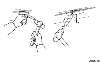
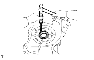
REMOVE TIMING CHAIN CASE OIL SEAL
Using a screwdriver and a hammer, tap out the oil seal.
HINT:
Tape the screwdriver tip before use.
21.
REMOVE NO. 1 CRANKSHAFT POSITION SENSOR PLATE
Remove the crankshaft position sensor plate.
22.
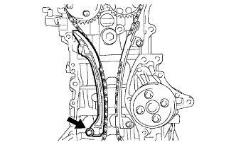
REMOVE TIMING CHAIN GUIDE
Remove the bolt and timing chain guide.
23.
REMOVE CHAIN TENSIONER SLIPPER
Remove the bolt and chain tensioner slipper.
24.
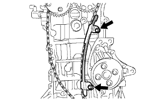
REMOVE NO. 1 CHAIN VIBRATION DAMPER
Remove the 2 bolts and chain vibration damper.
25.
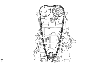
REMOVE CHAIN SUB-ASSEMBLY
Remove the chain sub-assembly.
26.
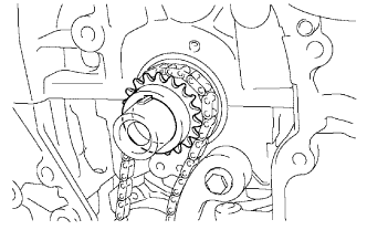
REMOVE CRANKSHAFT TIMING SPROCKET
Remove the crankshaft timing sprocket.
27.
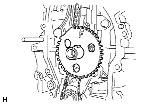
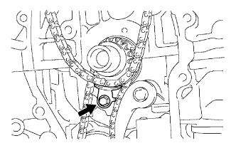
REMOVE NO. 2 CHAIN SUB-ASSEMBLY
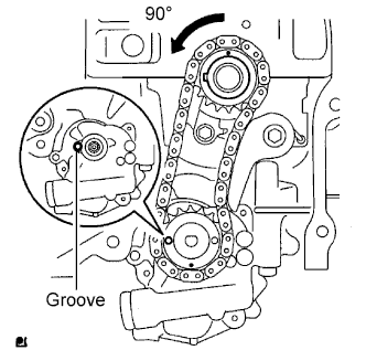
Turn the crankshaft 90° counterclockwise to align the adjusting hole of the oil pump drive shaft gear with the groove of the oil pump.
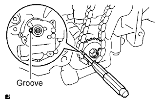
Insert a 4 mm diameter bar into the adjusting hole of the oil pump drive shaft gear to lock the gear in position, and then remove the nut.
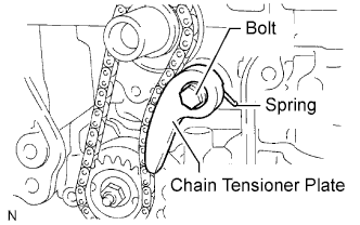
Remove the bolt, chain tensioner plate and spring.
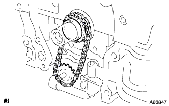
Remove the chain tensioner, oil pump drive shaft gear, oil pump drive gear and chain.
28.
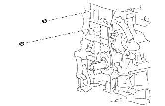
REMOVE KEYS
Remove the 2 pulley set keys from the crankshaft.
29.
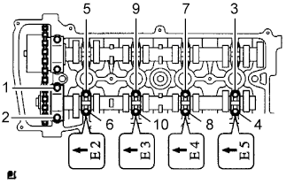
REMOVE NO. 2 CAMSHAFT
Using several steps, uniformly loosen and remove the 10 bearing cap bolts in the sequence shown in the illustration.
Remove the 5 bearing caps.
30.
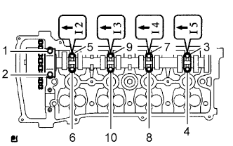
REMOVE CAMSHAFT
Using several steps, uniformly loosen and remove the 10 bearing cap bolts in the sequence shown in the illustration.
Remove the 5 bearing caps.
31.
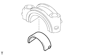
REMOVE NO. 1 CAMSHAFT BEARING
Remove the No. 1 camshaft bearing.
32.
REMOVE NO. 2 CAMSHAFT BEARING
Remove the No. 2 camshaft bearing.
33.
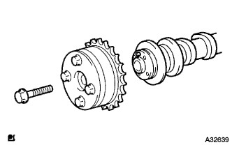
REMOVE CAMSHAFT TIMING SPROCKET
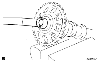
Clamp the camshaft in a vise.
Remove the flange bolt of the camshaft timing sprocket.
34.
REMOVE CAMSHAFT TIMING GEAR ASSEMBLY
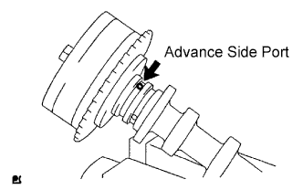
Clamp the camshaft in a vise, and make sure that the camshaft timing gear does not rotate.
Cover all the oil ports except the advance side port shown in the illustration with vinyl tape.
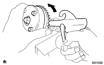
Apply air pressure of 100 kPa (1.0 kgf/cm2, 14 psi) to the oil path, then turn the camshaft timing gear in the advance direction (counterclockwise) by hand.
CAUTION:
Cover the paths with a shop rag or piece of cloth to keep oil from splashing.
HINT:
Depending on the air pressure, the camshaft timing gear will turn to the advance angle side without applying force by hand. Also, if the pressure is difficult to apply because of air leakage from the port, the lock may be difficult to release.
Remove the flange bolt of the camshaft timing gear.
NOTICE:
Be sure not to remove the other 4 bolts.
If the gear is to be reused, be sure to release the straight pin lock before installing the gear.
35.
REMOVE CYLINDER HEAD SUB-ASSEMBLY
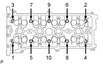
Using several steps, uniformly loosen and remove the 10 cylinder head set bolts and 10 plate washers with a 10 mm bi-hexagon wrench in the sequence shown in the illustration.
NOTICE:
Head warpage or cracking could result from removing the bolts in the wrong order.
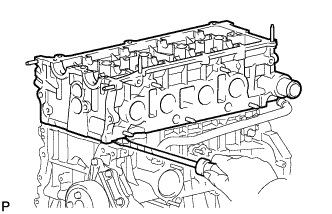
Using a screwdriver with its tip wrapped with tape, pry between the cylinder head and cylinder block, and remove the cylinder head.
NOTICE:
Be careful not to damage the contact surfaces of the cylinder head and cylinder block.
36.
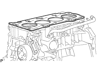
REMOVE CYLINDER HEAD GASKET
Remove the cylinder head gasket.
37.
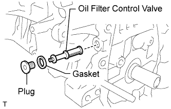
REMOVE OIL CONTROL VALVE FILTER
Using an 8 mm socket hexagon wrench, remove the plug and filter.
38.
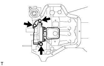
REMOVE OIL PUMP ASSEMBLY
Remove the 3 bolts, oil pump and gasket.
39.
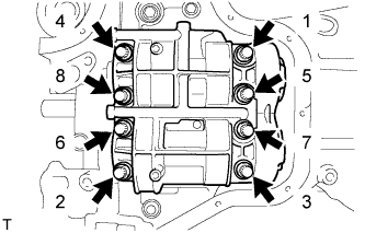
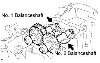
REMOVE NO. 1 AND NO. 2 BALANCESHAFT SUB-ASSEMBLY
Uniformly loosen and remove the 8 bolts in the sequence shown in the illustration.
Remove the No. 1 and No. 2 balanceshafts.
40.
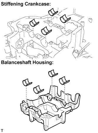
REMOVE NO. 1 BALANCESHAFT BEARING
Remove the balanceshaft bearings.
41.
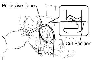
REMOVE ENGINE REAR OIL SEAL
Using a knife, cut off the oil seal lip.
Using a screwdriver with its tip taped, pry out the oil seal.
NOTICE:
After removing the oil seal, check the crankshaft for damage. If it is damaged, smooth the surface with 400-grit sandpaper.
42.
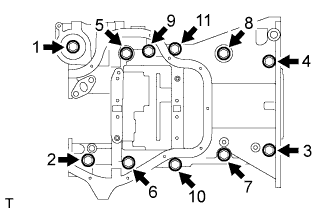
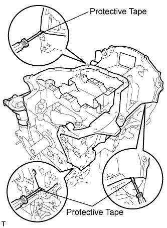
REMOVE STIFFENING CRANKCASE ASSEMBLY
Uniformly loosen and remove the 11 bolts in the sequence shown in the illustration.
Using a screwdriver, remove the crankcase by prying between the crankcase and cylinder block.
NOTICE:
Be careful not to damage the contact surfaces of the crankcase and cylinder block.
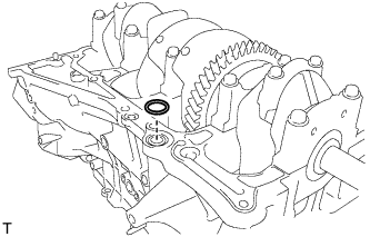
Remove the O-ring from the cylinder block.
43.
REMOVE PISTON SUB-ASSEMBLY WITH CONNECTING ROD
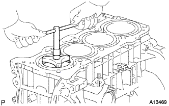
Using a ridge reamer, remove all the carbon from the top of the cylinder.
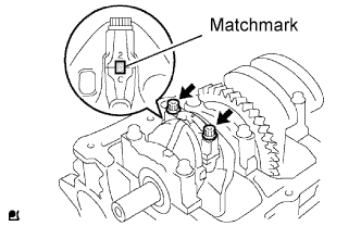
Check that the matchmarks on the connecting rod and cap are aligned to ensure correct reassembly.
HINT:
The matchmarks on the connecting rods and caps are provided to ensure correct reassembly.
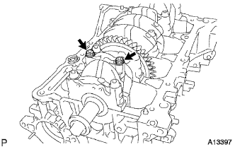
Using a 12 mm socket wrench, uniformly loosen the 2 bolts.
Using the 2 removed connecting rod cap bolts, remove the connecting rod cap and lower bearing by wiggling the connecting rod cap right and left.
HINT:
Keep the lower bearing inserted in the connecting rod cap.
Push the piston, connecting rod assembly and upper bearing through the top of the cylinder block.
HINT:
Keep the bearing, connecting rod and cap together.
Arrange the piston and connecting rod assemblies in the correct order.
44.
REMOVE CONNECTING ROD BEARING
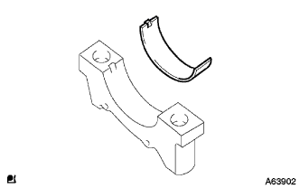
Remove the connecting rod bearings.
HINT:
Arrange the removed parts in the correct order.
45.
REMOVE PISTON RING SET
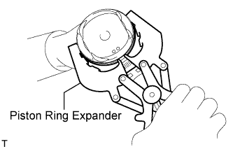
Using a piston ring expander, remove the 2 compression rings.
Remove the oil ring rail and oil ring expander by hand.
HINT:
Arrange the removed parts in the correct order.
46.
REMOVE PISTON PIN HOLE SNAP RING
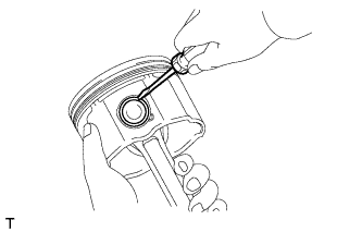
Using a screwdriver, pry out the 2 snap rings.
47.
REMOVE PISTON
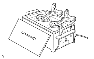
Gradually heat each piston to approximately 80 to 90°C (176 to 194°F).
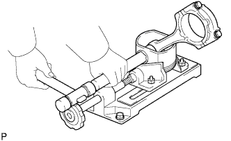
Using a plastic hammer and brass bar, lightly tap out the piston pin and remove the connecting rod.
HINT:
The piston and pin are a matched set.
Arrange the pistons, pins, rings, connecting rods and bearings in the correct order.
48.
REMOVE CRANKSHAFT
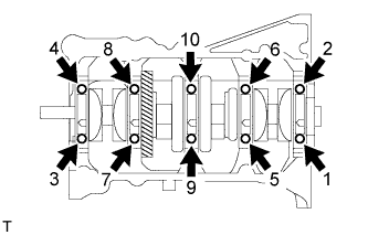
Uniformly loosen and remove the 10 main bearing cap bolts in the sequence shown in the illustration.
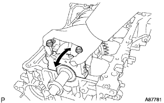
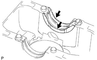
Use 2 removed main bearing cap bolts to remove the 5 main bearing caps and 5 lower bearings.
NOTICE:
Insert the bolts into the caps in turn. Ease the cap out by gently pulling up and applying force toward the front and back sides of the cylinder block, as shown in the illustration. Take care not to damage the contact surfaces of the cap and cylinder block.
HINT:
Keep the lower bearing and main bearing cap together.
Arrange the main bearing caps in the correct order.
Lift out the crankshaft.
49.
REMOVE UPPER CRANKSHAFT THRUST WASHER
Remove the upper crankshaft thrust washers from the cylinder block.
50.
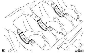
REMOVE CRANKSHAFT BEARING
Remove the 5 upper main bearings from the cylinder block.
HINT:
Arrange the bearings in the correct order.
51.
REMOVE NO. 2 CRANKSHAFT BEARING
Remove the 5 lower main bearings from the 5 main bearing caps.
HINT:
Arrange the bearings in the correct order.
52.
REMOVE STUD BOLT
53.
CLEAN CYLINDER BLOCK
NOTICE:
If the cylinder is washed at high temperatures, the cylinder liner will stick out beyond the cylinder block. Always wash the cylinder block at a temperature of 45°C (113°F) or less.