SYSTEM DESCRIPTION
Troubleshooting · Vehicles built Jun 2006 – Sep 2006
Versions by build date: Jun 2006 – Sep 2006 Oct 2006 – May 2009 from Jun 2009
| METER GAUGE |
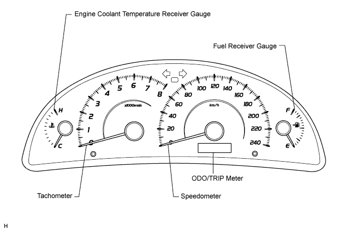
without Multi-information Display

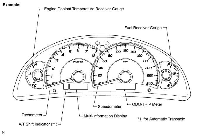
with Multi-information Display
METER GAUGE: Item
Detail
Speedometer
Indicates the vehicle speed receiving a signal from the skid control ECU. (CAN (CAN No. 1 Bus))
Tachometer
Indicates the engine speed based on a signal received from the ECM. (CAN (CAN No. 1 Bus))
Engine Coolant Temperature Receiver Gauge
Indicates the engine coolant temperature based on a signal received from the ECM. (CAN (CAN No. 1 Bus))
Fuel Receiver Gauge
Indicates the fuel level based on a signal the fuel sender gauge. (Direct Line)
WARNING/INDICATOR: Item
Detail
TURN SIGNAL
Receives a turn signal from the turn signal flasher. (Direct Line)
BEAM
Receives a beam signal from the main body ECU. (CAN (CAN No. 1 Bus))
CHARGE
Receives a charge light signal from the generator. (Direct Line)
CHECK E/G
Receives a check engine light signal from the ECM. (Direct Line)
DOOR
Open door indicator light comes on receiving a door condition signal from the main body ECU. (CAN (CAN MS Bus))
D-BELT
Receives a driver side seat belt signal from the center airbag sensor assembly. (CAN (CAN No. 1 Bus))
P-BELT (*5)
Receives a passenger side seat belt signal from the front passenger seat belt buckle switch and transmits a passenger side seat belt condition signal to the clock assembly. (Direct Line)
Fr FOG (*3)
Receives a front fog indicator light from the main body ECU. (CAN (CAN No. 1 Bus))
A/T SHIFT (*1)
Receives an A/T shift condition and A/T gear position signal from the park/neutral position switch and the ECM. (CAN (CAN No. 1 Bus))
FUEL
Receives a fuel signal from the fuel sender gauge. (Direct Line)
ABS
Receives an ABS signal from the skid control ECU. (CAN (CAN No. 1 Bus))
SLIP (*4)
Receives a slip signal from the skid control ECU. (CAN (CAN No. 1 Bus))
VSC (*4)
Receives a VSC signal from the skid control ECU. (CAN (CAN No. 1 Bus))
BRAKE
Receives a brake signal from the brake fluid level warning switch (Direct Line) and the skid control ECU. (CAN (CAN No. 1 Bus))
CRUISE
Receives a cruise signal from the ECM. (CAN (CAN No. 1 Bus))
AIRBAG
Receives an airbag signal from the center airbag sensor assembly. (CAN (CAN No. 1 Bus))
Oil pressure
Receives an oil pressure signal from the engine oil pressure switch. (Direct Line)
Speed limit (*5)
- Receives a vehicle speed signal from the skid control ECU.
- Meter CPU performs bulb check for 3 seconds when turning the ignition switch to the ON position.
- HINT:
- The multi-information display has been located below the tachometer.
- The display shows a message for each of the functions described in the table below.
- The multi-information display has been located below the tachometer.
*1: for Automatic TransaxleMULTI-INFORMATION DISPLAY (*6): Item
Detail
Cruise Information
- Outside Temperature (*7)
- Driving Range (*8)
- Average Fuel Consumption (*8)
- Distance driven since engine start (*8)
- Average speed since engine start (*8)
5 types of information (outside temperature, driving range, average fuel consumption, distance driven since engine start and average speed) can be displayed.
*2: for Australia
*3: with Front Fog Light
*4: with VSC
*5: for G.C.C. Countries
*6: with Multi-information Display
*7: with Outside Temperature Display
*8: with Cruise Information Display- Receives a vehicle speed signal from the skid control ECU.