SYSTEM DIAGRAM
System information · Vehicles built Jun 2006 – Sep 2006
Versions by build date: Jun 2006 – Sep 2006 from Oct 2006
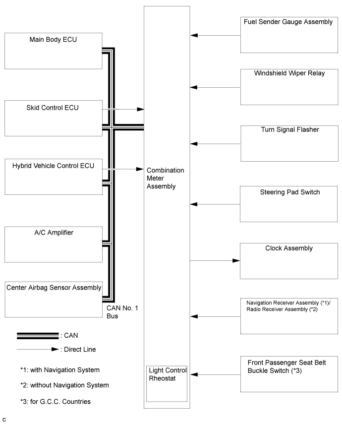

| Sender |
Receiver |
Communication Signal |
Communication Line |
| Combination Meter Assembly |
|
Vehicle speed signal |
CAN (CAN No. 1 Bus) |
|
Direct Line |
||
|
Rheostat duty signal |
CAN (CAN No. 1 Bus) |
|
| Tail cancel signal | |||
| Main Body ECU |
Lounge illumination signal |
CAN (CAN No. 1 Bus) |
|
|
Vehicle specification signal (Destination/Handle code) |
CAN (CAN No. 1 Bus) |
|
| Clock assembly |
Passenger seat belt warning light signal (*4) |
Direct Line |
|
| ECM |
Combination Meter Assembly |
Starter signal |
CAN (CAN No. 1 Bus) |
| Test mode signal | |||
| Cruise operation indicator (*5) | |||
| Cruise control warning (*5) | |||
| TM oil temperature range signal | |||
| Engine coolant temperature signal | |||
| Engine type information | |||
| Shift position signal (*6) | |||
| Engine RPM data | |||
| Check engine warning light signal |
Direct Line |
||
| Main Body ECU |
Combination Meter Assembly |
Illuminance data |
CAN (CAN No. 1 Bus) |
| Auto dimmer signal | |||
| ACC switch signal | |||
| Key switch signal | |||
| Each door courtesy switch signal | |||
| Slide roof signal (*7) | |||
| Driver side seat belt switch signal | |||
| Parking brake switch signal | |||
| High beam indicator light signal | |||
| Tail indicator light signal | |||
| Front fog indicator light signal | |||
|
Combination Meter Assembly |
Hood courtesy switch signal |
CAN (CAN MS Bus) |
| Certification ECU |
Combination Meter Assembly |
Meter buzzer request signal |
CAN (CAN MS Bus) |
| Each door open display signal | |||
| Skid Control ECU |
Combination Meter Assembly |
Vehicle speed signal |
CAN (CAN No. 1 Bus) |
| Brake warning light control flag | |||
| ABS warning light signal | |||
| Slip indicator light signal (*8) | |||
| VSC warning signal (*8) | |||
|
Combination Meter Assembly |
Diagnosis signal |
CAN (CAN No. 1 Bus) |
| A/C Amplifier |
Combination Meter Assembly |
Ambient temperature display signal |
CAN (CAN No. 1 Bus) |
| Center Airbag Sensor Assembly |
Combination Meter Assembly |
Airbag warning light signal |
CAN (CAN No. 1 Bus) |
| Steering Pad Switch |
Combination Meter Assembly |
Steering pad switch operation signal |
Direct Line |
| Oil Pressure Switch |
Combination Meter Assembly |
Engine oil pressure warning light signal |
Direct Line |
| Fuel Sender Gauge Assembly |
Combination Meter Assembly |
Fuel level signal |
Direct Line |
| Turn Signal Flasher |
Combination Meter Assembly |
Turn LH/RH indicator light signal |
Direct Line |
| Brake Fluid Level Warning Switch |
Combination Meter Assembly |
Brake fluid level warning light signal |
Direct Line |
| Front Passenger Seat Belt Buckle Switch (*4) |
Combination Meter Assembly |
Front passenger seat belt condition signal |
Direct Line |
| Generator |
Combination Meter Assembly |
Charge warning light signal |
Direct Line |
*2: with Navigation System
*3: for Australia
*4: for G.C.C. Countries
*5: with Cruise Control System
*6: for Automatic Transaxle
*7: with Sliding Roof
*8: with VSC
*9: with Auto Wiper System