Power Source Mode does not Change to ON (IG)
Circuit diagnosis · Vehicles built from Oct 2006
DESCRIPTION
When the engine switch is pushed with the electrical key in the cabin, the main body ECU receives signals to switch the power source mode.- HINT:
- To allow use of the intelligent tester to inspect the push-button start function when the engine switch is off, repeat opening and closing any of the doors. Opening and closing a door establishes communication between the intelligent tester and the main body ECU. (Opening and closing a door can also be simulated by operating a door courtesy light switch.)
WIRING DIAGRAM
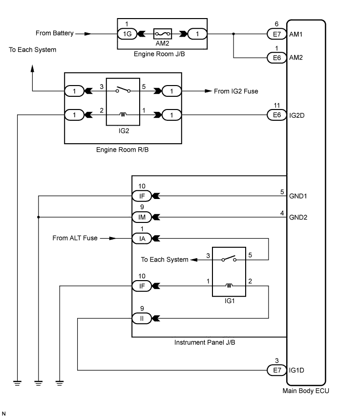

INSPECTION PROCEDURE
| 1. INSPECT FUSE (AM2) |

Remove the AM2 fuse from the engine room J/B.
Measure the resistance of the fuse.
- Standard resistance:
- Below 1 Ω
|
|
||||

| OK | |
 |
| 2. CHECK CONNECTORS |
Check that the connectors are securely connected and the terminals are not deformed or loose.
- OK:
- The connectors are securely connected and the terminals are not deformed or loose.
|
|
||||
| OK | |
|
| 3. CHECK HARNESS AND CONNECTOR (MAIN BODY ECU - BATTERY) |
Disconnect the E6 and E7 ECU connectors.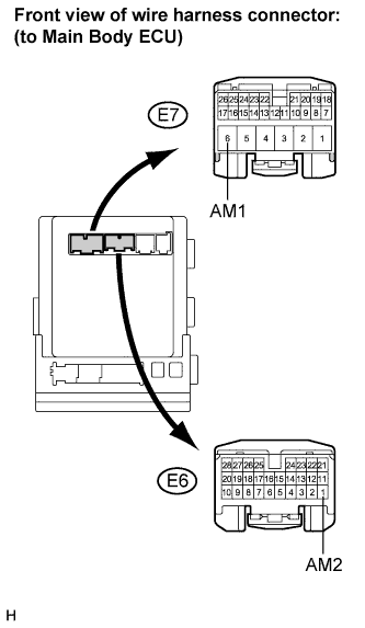
Measure the voltage according to the value(s) in the table below.
- Standard voltage:
Tester Connection
Condition
Specified Condition
E7-6 (AM1) - Body ground
Always
11 to 14 V
E6-1 (AM2) - Body ground
Always
11 to 14 V
|
|
||||
| OK | |
|
| 4. CHECK HARNESS AND CONNECTOR (MAIN BODY ECU - BODY GROUND) |
Disconnect the IF and IM ECU connectors.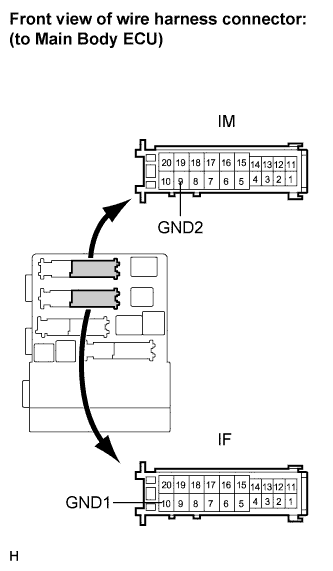
Measure the resistance according to the value(s) in the table below.
- Standard resistance:
Tester Connection
Condition
Specified Condition
IF-10 (GND1) - Body ground
Always
Below 1 Ω
IM-9 (GND2) - Body ground
Always
Below 1 Ω
|
|
||||
| OK | |
|
| 5. INSPECT RELAY (IG2 RELAY) |
Remove the IG2 relay from the engine room R/B No. 2.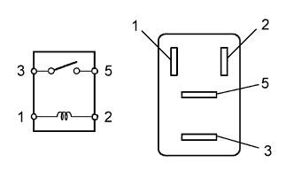
Measure the resistance according to the value(s) in the table below.
- Standard resistance:
Tester Connection
Condition
Specified Condition
3 - 5
When battery voltage is not applied to terminals 1 and 2
10 kΩ or higher
3 - 5
When battery voltage is applied to terminals 1 and 2
Below 1 Ω
|
|
||||
| OK | |
|
| 6. CHECK HARNESS AND CONNECTOR (ENGINE ROOM RELAY BLOCK - MAIN BODY ECU AND BODY GROUND) |
Remove the IG2 relay from the engine room R/B.
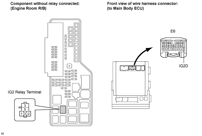
Disconnect the E6 ECU connector.
Measure the resistance according to the value(s) in the table below.
- Standard resistance:
Tester Connection
Condition
Specified Condition
Engine room R/B IG2 relay terminal 1 - E6-11 (IG2D)
Always
Below 1 Ω
Engine room R/B IG2 relay terminal 2 - Body ground
Below 1 Ω
E6-11 (IG2D) - Body ground
10 kΩ or higher
|
|
||||
| OK | |
|
| 7. INSPECT RELAY (IG1 RELAY) |
Remove the IG1 relay from the instrument panel J/B.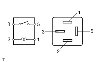
Measure the resistance according to the value(s) in the table below.
- Standard resistance:
Tester Connection
Condition
Specified Condition
3 - 5
When battery voltage is not applied to terminals 1 and 2
10 kΩ or higher
3 - 5
When battery voltage is applied to terminals 1 and 2
Below 1 Ω
|
|
||||
| OK | |
|
| 8. CHECK HARNESS AND CONNECTOR (INSTRUMENT PANEL JUNCTION BLOCK - MAIN BODY ECU) |
Disconnect the II J/B connector.
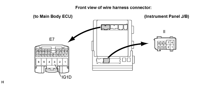
Disconnect the E7 ECU connector.
Measure the resistance according to the value(s) in the table below.
- Standard resistance:
Tester Connection
Condition
Specified Condition
II-9 - E7-3 (IG1D)
Always
Below 1 Ω
E7-3 (IG1D) - Body ground
Always
10 kΩ or higher
|
|
||||
| OK | |
|
| 9. CHECK HARNESS AND CONNECTOR (INSTRUMENT PANEL JUNCTION BLOCK - BATTERY AND BODY GROUND) |
Disconnect the IF and IA J/B connectors.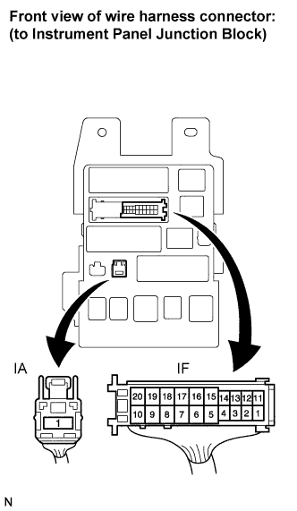
Measure the resistance according to the value(s) in the table below.
- Standard resistance:
Tester Connection
Condition
Specified Condition
IF-10 - Body ground
Always
Below 1 Ω
Measure the voltage according to the value(s) in the table below.
- Standard voltage:
Tester Connection
Condition
Specified Condition
IA-1 - Body ground
Always
11 to 14 V
|
|
||||
| OK | |
|
| 10. INSPECT INSTRUMENT PANEL JUNCTION BLOCK |
Measure the resistance according to the value(s) in the table below.
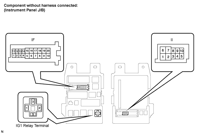
- Standard resistance:
Tester Connection
Condition
Specified Condition
IF-10 - Instrument Panel J/B - IG1 relay terminal-1
Always
Below 1 Ω
II-9 - Instrument Panel J/B IG1 relay terminal-2
Always
Below 1 Ω
IF-10 - Body ground
Always
10 kΩ or higher
II-9 - Body ground
Always
10 kΩ or higher
|
|
||||
| OK | ||
 |
||
| ||