INSTALLATION
Removal / installation · Vehicles built Oct 2006 – May 2009
Versions by build date: Jun 2006 – Sep 2006 Oct 2006 – May 2009 from Jun 2009
| 1.
INSTALL BRAKE PEDAL SUPPORT ASSEMBLY (for LHD) |
 |
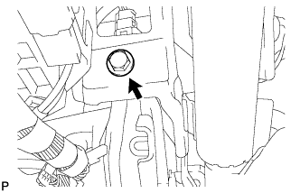
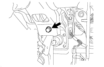
- Temporarily install the brake pedal support assembly with the bolt.
- NOTICE:
- Fully tighten the bolt after installing the brake booster assembly.
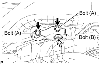
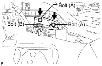
- Temporarily install the No. 1 brake pedal support plate with 2 bolts (A) and bolt (B).
- NOTICE:
- Fully tighten 2 bolts (A) and bolt (B) after installing the brake booster assembly.
Install the brake booster assembly (Click here).
- Fully tighten the bolt.
-
Torque:
- 19 N*m{
194 kgf*cm
, 14 ft.*lbf
}
- Fully tighten 2 bolts (A) and bolt (B).
-
Torque:
- Bolt (A):
- 19 N*m{
194 kgf*cm
, 14 ft.*lbf
}
- Bolt (B):
- 13 N*m{
133 kgf*cm
, 10 ft.*lbf
}
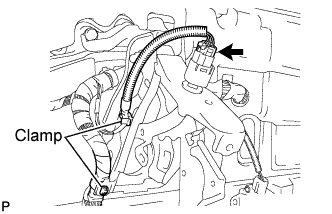
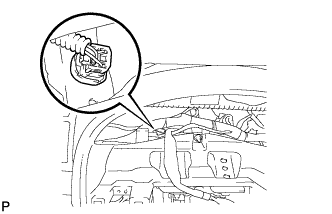
- Engage the 2 clamps and connect the stop light switch connector.
| 2.
INSTALL BRAKE PEDAL SUPPORT ASSEMBLY (for RHD) |
|
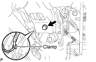
- Temporarily install the brake pedal support assembly with the bolt and install the clamp.
- Temporarily install the No. 1 brake pedal support plate with 2 bolts (A) and bolt (B).
- NOTICE:
- Fully tighten 2 bolts (A) and bolt (B) after installing the brake booster assembly.
Install the brake booster assembly. (Click here)
- Fully tighten the bolt.
-
Torque:
- 19 N*m{
194 kgf*cm
, 14 ft.*lbf
}
- Fully tighten 2 bolts (A) and bolt (B).
-
Torque:
- Bolt (A):
- 19 N*m{
194 kgf*cm
, 14 ft.*lbf
}
- Bolt (B):
- 13 N*m{
133 kgf*cm
, 10 ft.*lbf
}
- Connect the stop light switch connector.
| 3.
INSTALL ACCELERATOR PEDAL ASSEMBLY (for RHD)
|
|
- NOTICE:
- Avoid physical shock to the accelerator pedal assembly.
- Do not disassemble the accelerator pedal assembly.
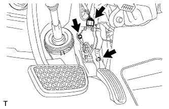
- Install the accelerator pedal assembly with the 2 bolts.
-
Torque:
- 5.4 N*m{
55 kgf*cm
, 48 in.*lbf
}
Connect the accelerator pedal connector.
| 4.
INSTALL HEADLIGHT LEVELING ECU ASSEMBLY (w/ Headlight Leveling)
|
|
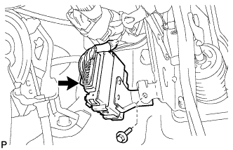
- Install the headlight leveling ECU assembly with the bolt.
Connect the connector.
| 5.
INSTALL AFS ECU (w/ AFS)
|
|
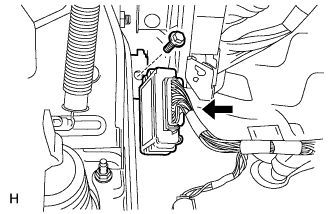
- Install the AFS ECU with the bolt.
Connect the connector.
| 6.
INSTALL BRAKE BOOSTER ASSEMBLY |
|
- HINT:
- Refer to the procedures up to "INSTALL BRAKE BOOSTER". (Click here)
| 7.
INSTALL COMBINATION METER ASSEMBLY
|
|
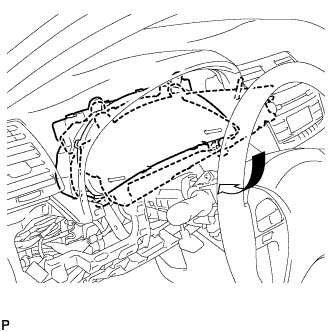
Connect the connector.
- Install the combination meter assembly as shown in the illustration.
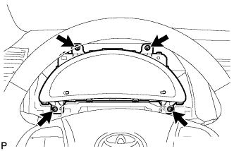
- Install the 4 screws.
| 8.
INSTALL INSTRUMENT CLUSTER FINISH PANEL SUB-ASSEMBLY
|
|
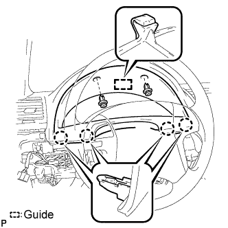
- Engage the guide and the 4 claws.
Install the instrument cluster finish panel sub-assembly with the 2 clips.
| 9.
INSTALL LOWER INSTRUMENT PANEL FINISH PANEL (w/o Smart Entry and Start System)
|
|
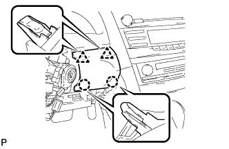
- Engage the 2 claws and 2 clips to install the lower instrument panel finish panel.
| 10.
INSTALL LOWER INSTRUMENT PANEL FINISH PANEL (w/ Smart Entry and Start System)
|
|
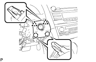
- Connect the connector.
Engage the 2 claws and 2 clips to install the lower instrument panel finish panel.
| 11.
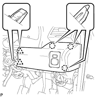
INSTALL NO. 1 INSTRUMENT PANEL SUB-ASSEMBLY (for LHD)
|
|
Connect each connector.
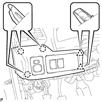
- Engage the 3 claws and 2 clips to install the No. 1 instrument panel sub-assembly.
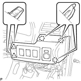
| 12.
INSTALL NO. 1 INSTRUMENT PANEL SUB-ASSEMBLY (for 2AZ-FE RHD)
|
|
Connect each connector.
- Engage the 3 claws and 2 clips to install the No. 1 instrument panel sub-assembly.
| 13.
INSTALL NO. 1 INSTRUMENT PANEL SUB-ASSEMBLY (for 2GR-FE RHD)
|
|
Connect each connector.
- Engage the 3 claws and 2 clips to install the No. 1 instrument panel sub-assembly.
| 14.
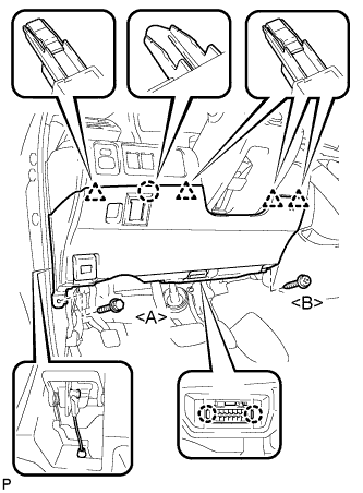
INSTALL LOWER NO. 1 INSTRUMENT PANEL FINISH PANEL (except 2GR-FE RHD)
|
|
- Install the air hose and connect the connector.
Engage the 2 claws and the DLC3.
Engage the claw and the 4 clips.
Install the lower No. 1 instrument panel finish panel with the screw <B> and bolt <A>.
| 15.
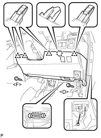
INSTALL LOWER NO. 1 INSTRUMENT PANEL FINISH PANEL (for 2GR-FE RHD)
|
|
- Install the air hose and connect each connector.
Engage the claw and the 4 clips.
Engage the 2 claws and the DLC3.
Install the lower No. 1 instrument panel finish panel with the screw <F> and bolt <D>.
| 16.
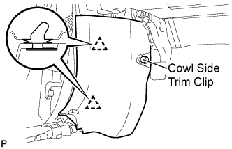
INSTALL COWL SIDE TRIM SUB-ASSEMBLY LH
|
|
- Engage the 2 clips.
Install the cowl side trim sub-assembly LH with the cowl side trim clip.
| 17.
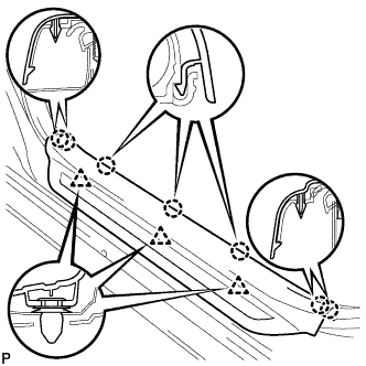
INSTALL FRONT DOOR SCUFF PLATE LH
|
|
- Engage the 7 claws and 3 clips, then install the front door scuff plate LH.