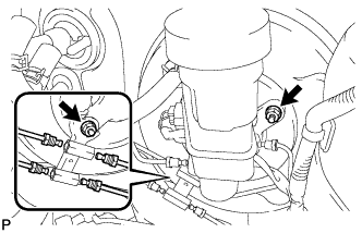
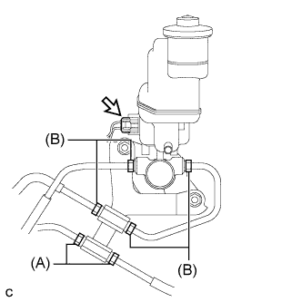
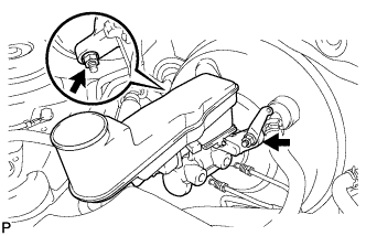
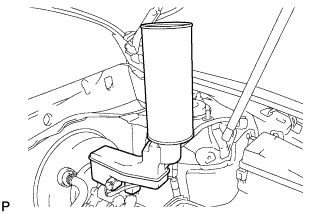
Connect the clutch reservoir tube to the brake master cylinder sub-assembly and move the clip.
5.
FILL RESERVOIR WITH BRAKE FLUID
Fill the reservoir with brake fluid.
Fluid:
SAE J1703 or FMVSS No. 116 DOT3
6.
BLEED MASTER CYLINDER
HINT:
If the master cylinder is reinstalled or if the reservoir becomes empty, bleed the air from the master cylinder.
To avoid brake fluid from contacting and/or damaging, cover the painted surface with a shop rag or a piece of cloth.
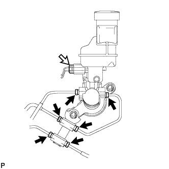
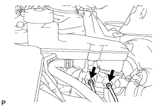
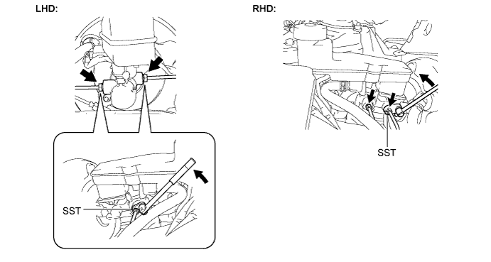
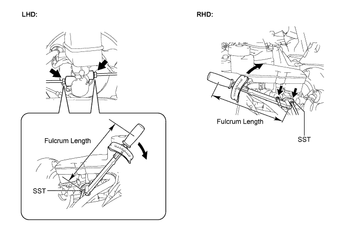
Using SST, disconnect the 2 brake lines from the master cylinder.
SST
09023-00101 09023-38201
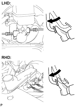
Slowly depress the brake pedal and hold it (*1).
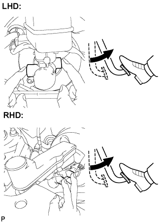
Cover the 2 outer holes with fingers, and release the brake pedal (*2).
Repeat (*1) and (*2) 3 or 4 times.
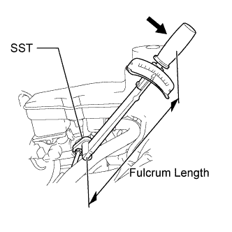
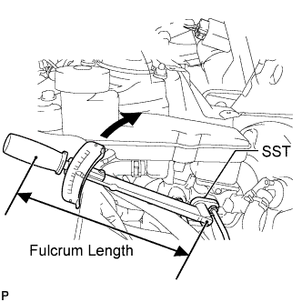
Using SST, connect the 2 brake lines to the master cylinder.
SST
09023-00101 09023-38201
Torque:
Without SST without VSC:
15 N*m{
155 kgf*cm
, 11 ft.*lbf
}
With SST without VSC:
14 N*m{
143 kgf*cm
, 10 ft.*lbf
}
Without SST with VSC:
20 N*m{
204 kgf*cm
, 15 ft.*lbf
}
With SST with VSC:
18 N*m{
183 kgf*cm
, 13 ft.*lbf
}
NOTICE:
Use a torque wrench with a fulcrum length of 250 mm (9.84 in.).
This torque value is effective when SST is parallel to a torque wrench.
7.
BLEED BRAKE LINE
NOTICE:
Bleed the air from the brake line of the wheel farthest from the master cylinder.
Connect a vinyl tube to the bleeder plug.
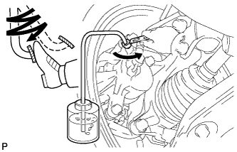
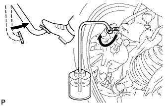
Depress the brake pedal several times, then loosen the bleeder plug with the pedal depressed (*3).
When fluid stops coming out, tighten the bleeder plug, then release the brake pedal (*4).
Repeat (*3) and (*4) until all the air in the fluid is completely bled out.
Tighten the bleeder plug completely.
Torque:
12 N*m{
122 kgf*cm
, 9 ft.*lbf
}
Repeat the above procedures for each wheel to bleed the air from the brake line.
8.
BLEED CLUTCH PIPE LINE (for Manual Transaxle)
Fill the brake reservoir with brake fluid and bleed the clutch system.
Torque:
8.3 N*m{
85 kgf*cm
, 74 in.*lbf
}
9.
INSPECT FLUID LEVEL IN RESERVOIR
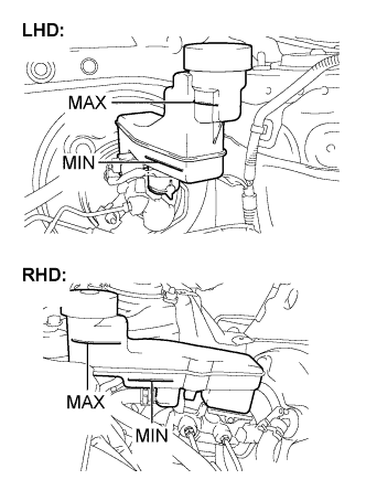
Check the fluid level. If brake fluid level is low, check for leakage and inspect the disc brake pad. If necessary, refill the reservoir with brake fluid after repair and replacement.
Fluid:
SAE J1703 or FMVSS No. 116 DOT3
10.
INSPECT FOR FLUID LEAK
11.
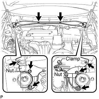
INSTALL COWL TOP OUTER FRONT PANEL SUB-ASSEMBLY
Install the cowl top outer front panel sub-assembly with the 4 nuts, the 4 bolts and the clamp.
Torque:
Nut:
85 N*m{
867 kgf*cm
, 63 ft.*lbf
}
Bolt:
5.0 N*m{
51 kgf*cm
, 44 in.*lbf
}
12.
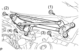
INSTALL WINDSHIELD WIPER MOTOR AND LINK ASSEMBLY
Install the windshield wiper motor and link assembly with the 4 bolts.
Torque:
7.5 N*m{
77 kgf*cm
, 66 in.*lbf
}
NOTICE:
Tighten the bolts in the order shown in the illustration.
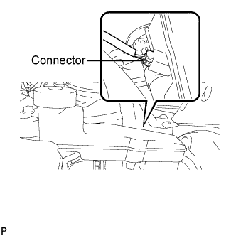
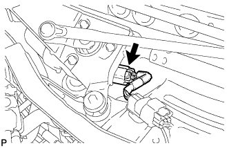
Connect the connector.
13.
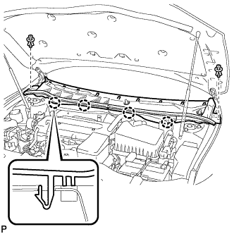
INSTALL COWL TOP VENTILATOR LOUVER SUB-ASSEMBLY
Engage the 4 claws and install the cowl top ventilator louver sub-assembly.
Install the 2 clips.
14.
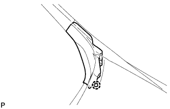
INSTALL FRONT FENDER TO COWL SIDE SEAL LH
Engage the claw and install the front fender to cowl side seal LH.
15.
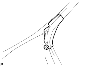
INSTALL FRONT FENDER TO COWL SIDE SEAL RH
Engage the claw and install the front fender to cowl side seal RH.
16.
INSTALL FRONT WIPER ARM AND BLADE ASSEMBLY LH
Operate the wiper and stop the windshield wiper motor at the automatic stop position.
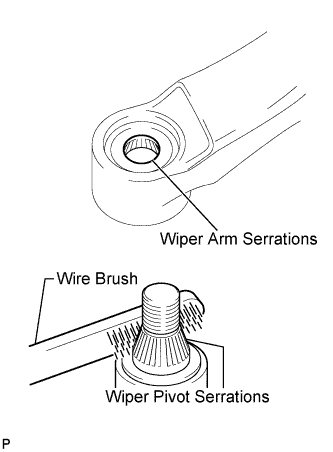
Clean the wiper arm serrations.
When reinstalling:
Clean the wiper pivot serrations with a wire brush.
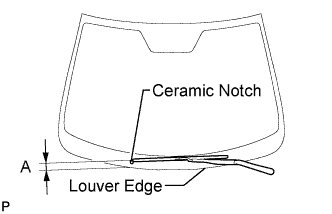
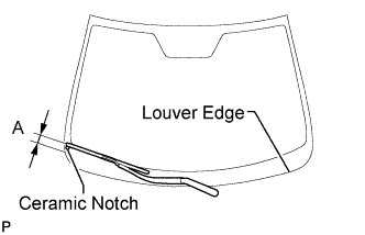
Install the front wiper arm and blade assembly LH with the nut to the position shown in the illustration.
Torque:
20 N*m{
204 kgf*cm
, 15 ft.*lbf
}
HINT:
Hold the arm hinge by hand to fasten the nut.
Area
Measurement
A
37 to 52 mm (1.46 to 2.05 in.)
17.
INSTALL FRONT WIPER ARM AND BLADE ASSEMBLY RH
Operate the wiper and stop the windshield wiper motor at the automatic stop position.
Clean the wiper arm serrations.
When reinstalling:
Clean the wiper pivot serrations with a wire brush.
Install the front wiper arm and blade assembly RH with the nut to the position shown in the illustration.
Torque:
20 N*m{
204 kgf*cm
, 15 ft.*lbf
}
HINT:
Hold the arm hinge by hand to fasten the nut.
Area
Measurement
A
23 to 38 mm (0.90 to 1.49 in.)
Operate the front wipers while spraying washer fluid on the windshield glass. Make sure that the front wipers function properly and the wipers do not come into contact with the vehicle body.
18.
INSTALL AIR CLEANER FILTER ELEMENT SUB-ASSEMBLY (for LHD)
19.
INSTALL AIR CLEANER CAP SUB-ASSEMBLY (for LHD)