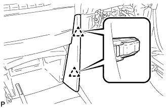
INSTALLATION
Removal / installation · Vehicles built from Jun 2009
Versions by build date: Jun 2006 – Sep 2006 Oct 2006 – May 2009 from Jun 2009
| 1.
INSTALL PARKING BRAKE LEVER SUB-ASSEMBLY |
 |
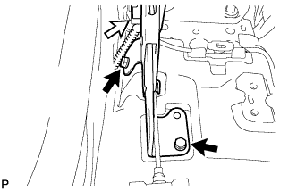
- Install the parking brake lever sub-assembly with the 2 bolts.
-
Torque:
- 21 N*m{
214 kgf*cm
, 15 ft.*lbf
}
Connect the parking brake switch connector.
| 2.
INSTALL PARKING BRAKE EQUALIZER |
|
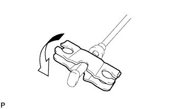
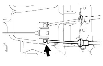
- Install the parking brake equalizer to the No. 1 parking brake cable assembly.
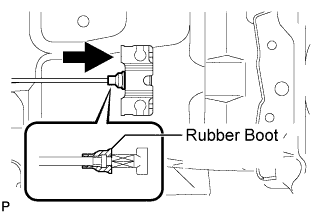
- Slide the rubber boot back as shown in the illustration.
| 3.
INSTALL NO. 2 PARKING BRAKE CABLE ASSEMBLY |
|
- Connect the No. 2 parking brake cable assembly to the parking brake equalizer.
| 4.
INSTALL NO. 3 PARKING BRAKE CABLE ASSEMBLY |
|
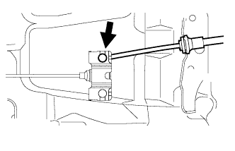
- Connect the No. 3 parking brake cable assembly to the parking brake equalizer.
| 5.
INSPECT PARKING BRAKE LEVER TRAVEL
|
|
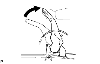
Pull the parking brake lever firmly.
Release the parking brake lock, and return the parking brake lever to its off position.
- Slowly pull the parking brake lever all the way up, and count the number of clicks.
- Parking brake lever travel:
- 7 to 9 notches at 200 N (20 kgf, 45 lbf)
| 6.
ADJUST PARKING BRAKE LEVER TRAVEL
|
|
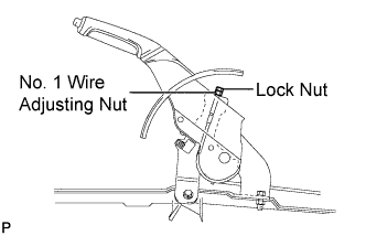
Pull up the parking brake lever. Hold the No. 1 wire adjusting nut using a wrench and loosen the lock nut.
Release the parking brake lever.
- Turn the No. 1 wire adjusting nut until the parking brake lever travel meets the above specification.
Hold the No. 1 wire adjusting nut using a wrench or an equivalent tool and tighten the lock nut.
-
Torque:
- 5.0 N*m{
51 kgf*cm
, 44 in.*lbf
}
Count the number of clicks after pulling and releasing the parking brake lever 3 or 4 times.
Check whether the parking brake drags.
When operating the parking brake lever, check that the parking brake indicator light comes on.
| 7.
INSTALL CONSOLE BOX ASSEMBLY
|
|
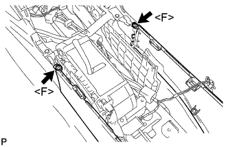
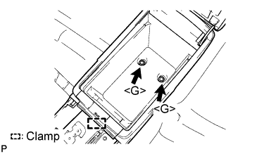
- Install the 2 screws <F>.
- Install the console box assembly with the 2 bolts <G>.
Engage the clamp.
| 8.
INSTALL CONSOLE BOX CARPET
|
|
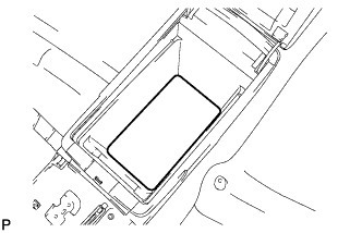
- Install the console box carpet.
| 9.
INSTALL CONSOLE BOX POCKET
|
|
Install the console box pocket.
| 10.
INSTALL UPPER CONSOLE REAR PANEL SUB-ASSEMBLY (for Manual Transaxle)
|
|
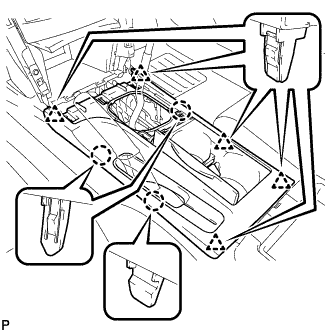
- Engage the 3 claws and 5 clips to install the upper console rear panel sub-assembly.
| 11.
INSTALL UPPER CONSOLE REAR PANEL SUB-ASSEMBLY (for Automatic Transaxle)
|
|
- Engage the 3 claws and 5 clips to install the upper console rear panel sub-assembly.
| 12.
INSTALL UPPER CONSOLE PANEL (for Manual Transaxle)
|
|
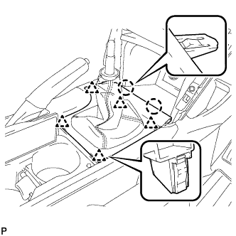
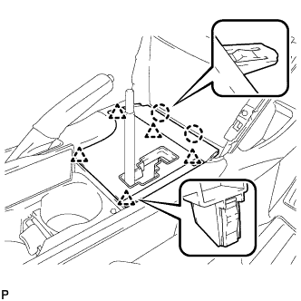
- Engage the 2 claws and the 5 clips to install the upper console panel as shown in the illustration.
| 13.
INSTALL POSITION INDICATOR HOUSING ASSEMBLY (for Automatic Transaxle)
|
|
- Engage the 2 claws and the 5 clips to install the position indicator housing assembly as shown in the illustration.
| 14.
INSTALL SHIFT LEVER KNOB SUB-ASSEMBLY (for Manual Transaxle)
|
|
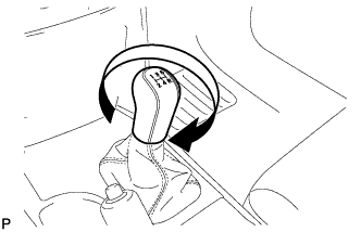
- Install the shift lever knob sub-assembly.
| 15.
INSTALL SHIFT LEVER KNOB SUB-ASSEMBLY (for Automatic Transaxle)
|
|
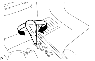
- Install the shift lever knob sub-assembly.
| 16.
INSTALL NO. 2 INSTRUMENT CLUSTER FINISH PANEL GARNISH
|
|
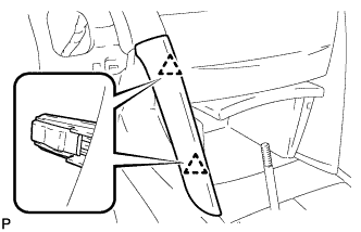
- Engage the 2 clips and install the No. 2 instrument cluster finish panel garnish.
| 17.
INSTALL NO. 1 INSTRUMENT CLUSTER FINISH PANEL GARNISH
|
|
- Engage the 2 clips and install the No. 1 instrument cluster finish panel garnish.