Home › BODY ELECTRICAL › OTHER SYSTEM › POWER OUTLET SOCKET (except 2GR-FE RHD)INSTALLATION
Removal / installation · Vehicles built from Jun 2009
Versions by build date: Jun 2006 – Sep 2006 Oct 2006 – May 2009 from Jun 2009
1.
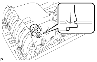
INSTALL REAR POWER OUTLET SOCKET COVER (for Automatic Transaxle LHD)
Engage the 2 claws and install the rear power outlet socket cover.
2.
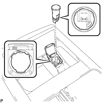
INSTALL REAR POWER OUTLET SOCKET ASSEMBLY (for Automatic Transaxle LHD)
Referring to the shape of the parts, align the rear power outlet socket assembly with the rear power outlet socket cover and install the rear power outlet socket assembly.
3.
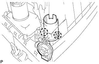
INSTALL FRONT POWER OUTLET SOCKET COVER
Engage the 2 claws and install the front power outlet socket cover.
4.
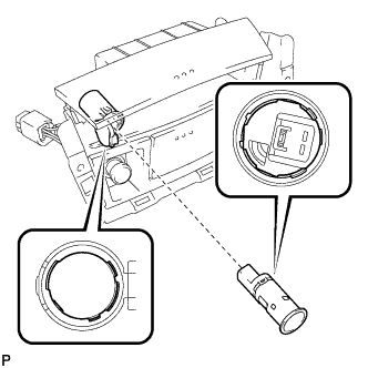
INSTALL FRONT POWER OUTLET SOCKET ASSEMBLY
Referring to the shape of the parts, align the front power outlet socket assembly with the front power outlet socket cover and install the front power outlet socket assembly.
5.
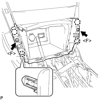
INSTALL UPPER CONSOLE PANEL SUB-ASSEMBLY
Connect each connector.
Engage the 4 claws. Install the upper console panel sub-assembly with the 2 screws <F>.
6.
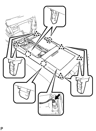
INSTALL UPPER CONSOLE REAR PANEL SUB-ASSEMBLY (for Automatic Transaxle LHD)
Connect the connector. Engage the 3 claws and 5 clips to install the upper console rear panel sub-assembly.
7.
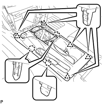
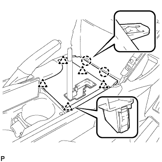
INSTALL UPPER CONSOLE REAR PANEL SUB-ASSEMBLY (for Automatic Transaxle RHD)
Engage the 3 claws and 5 clips to install the upper console rear panel sub-assembly.
8.
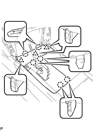
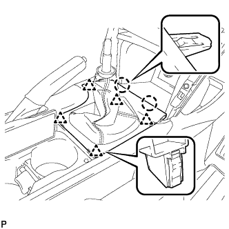
INSTALL UPPER CONSOLE REAR PANEL SUB-ASSEMBLY (for Manual Transaxle)
Engage the 3 claws and 5 clips to install the upper console rear panel sub-assembly.
9.
INSTALL POSITION INDICATOR HOUSING ASSEMBLY (for Automatic Transaxle LHD)
Engage the 6 claws and the 3 clips to install the position indicator housing assembly.
10.
INSTALL POSITION INDICATOR HOUSING ASSEMBLY (for Automatic Transaxle RHD)
Engage the 2 claws and the 5 clips to install the position indicator housing assembly as shown in the illustration.
11.
INSTALL UPPER CONSOLE PANEL (for Manual Transaxle)
Engage the 2 claws and the 5 clips to install the upper console panel as shown in the illustration.
12.
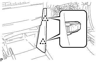
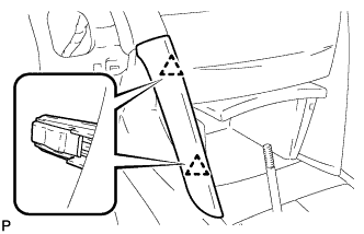
INSTALL NO. 1 INSTRUMENT CLUSTER FINISH PANEL GARNISH
Engage the 2 clips and install the No. 1 instrument cluster finish panel garnish.
13.
INSTALL NO. 2 INSTRUMENT CLUSTER FINISH PANEL GARNISH
Engage the 2 clips and install the No. 2 instrument cluster finish panel garnish.
14.
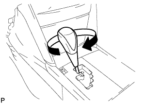
INSTALL SHIFT LEVER KNOB SUB-ASSEMBLY (for Automatic Transaxle LHD)
Install the shift lever knob sub-assembly.
15.
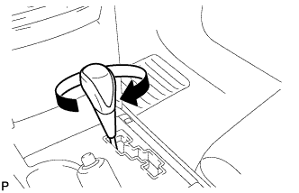
INSTALL SHIFT LEVER KNOB SUB-ASSEMBLY (for Automatic Transaxle RHD)
Install the shift lever knob sub-assembly.
16.
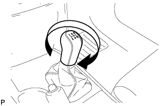
INSTALL SHIFT LEVER KNOB SUB-ASSEMBLY (for Manual Transaxle)
Install the shift lever knob sub-assembly.