Clock Loses or Gains Time
Circuit diagnosis · Vehicles built from Oct 2006
DESCRIPTION
Clock assembly receives time (Hour and Minute) adjust signals from the hazard warning switch. The whole hazard warning switch should be replaced if the time adjust button has a malfunction because this part is not independently supplied.- HINT:
- The maximum clock assembly margin of error is -4 to 4 seconds per day when the temperature is between -20°C (-4°F) and 60°C (140°F).
- If the clock assembly error is greater than specified above, replace the clock assembly.
- The maximum clock assembly margin of error is -4 to 4 seconds per day when the temperature is between -20°C (-4°F) and 60°C (140°F).
WIRING DIAGRAM
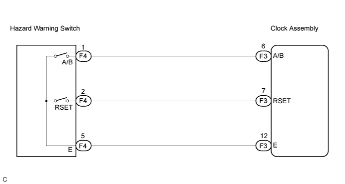

INSPECTION PROCEDURE
| 1. INSPECT HAZARD WARNING SWITCH |

Remove the hazard warning switch.
Measure the resistance according to the value(s) in the table below.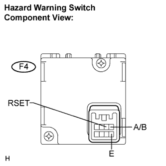
- Standard resistance:
Tester Connection
Condition
Specified Condition
F4-1 (A/B) - F4-5 (E)
H switch is not pressed
10 kΩ or higher
H switch is pressed
Below 1 Ω
F4-2 (RSET) - F4-5 (E)
M switch is not pressed
10 kΩ or higher
M switch is pressed
Below 1 Ω
|
|
||||

| OK | |
 |
| 2. CHECK HARNESS AND CONNECTOR (CLOCK ASSEMBLY - HAZARD WARNING SWITCH) |
Disconnect F3 and F4 connectors.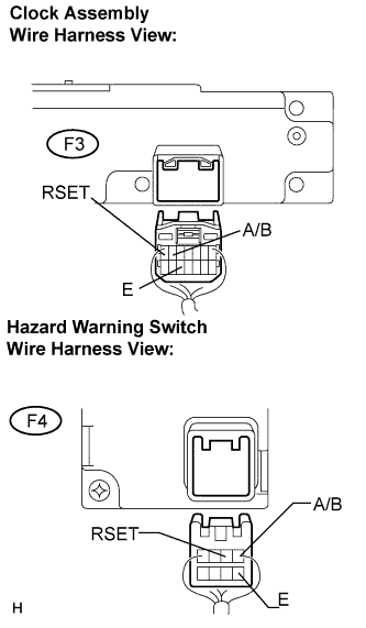
Measure the resistance according to the value(s) in the table below.
- Standard resistance:
Tester Connection
Condition
Specified Condition
F3-6 (A/B) - F4-1 (A/B)
Always
Below 1 Ω
F3-7 (RSET) - F4-2 (RSET)
Always
Below 1 Ω
F3-12 (E) - F4-5 (E)
Always
Below 1 Ω
F3-6 (A/B) - Body ground
Always
10 kΩ or higher
F3-7 (RSET) - Body ground
Always
10 kΩ or higher
|
|
||||
| OK | ||
 |
||
| ||