Park / Neutral Position Switch Circuit
Circuit diagnosis · Vehicles built from Jun 2009
DESCRIPTION
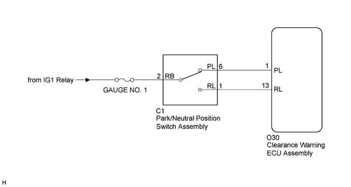
The clearance warning ECU assembly receives a reverse or park position signal from the park/neutral position switch.WIRING DIAGRAM

INSPECTION PROCEDURE
| 1. CHECK HARNESS AND CONNECTOR (BATTERY - PARK/NEUTRAL POSITION SWITCH) |

Disconnect the C1 connector from the park/neutral position switch assembly.
Measure the voltage according to the value(s) in the table below.
- Standard Voltage:
Tester Connection
Condition
Specified Condition
C1-2 (RB) - Body ground
Ignition switch on (IG)
11 to 14 V
|
|
||||

| OK | |
 |
| 2. INSPECT PARK/NEUTRAL POSITION SWITCH ASSEMBLY |
Remove the park/neutral position switch assembly.
Measure the resistance according to the value(s) in the table below when the shift lever is moved to each position.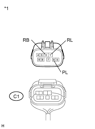
- Standard Resistance:
Tester Connection
Shift Position
Specified Condition
C1-2 (RB) - C1-6 (PL)
P
Below 1 Ω
Except P
10 kΩ or higher
C1-2 (RB) - C1-1 (RL)
R
Below 1 Ω
Except R
10 kΩ or higher
Text in Illustration *1
Component without harness connected
(Park/Neutral Position Switch Assembly)
|
|
||||
| OK | |
|
| 3. INSPECT CLEARANCE WARNING ECU ASSEMBLY |
Reconnect the C1 connector to the park/neutral position switch assembly.
Disconnect the O30 connector from the clearance warning ECU assembly.
Turn the ignition switch on (IG), and measure the voltage according to the value(s) in the table below when the shift lever is moved to each position.
- Standard Voltage:
Tester Connection
Shift Position
Specified Condition
O30-1 (PL) - Body ground
P
11 to 14 V
Except P
Below 1 V
O30-13 (RL) - Body ground
R
11 to 14 V
Except R
Below 1 V
|
|
||||
| OK | ||
 |
||
| ||