2006-2011 Camry Aurion · Service Manual BODY ELECTRICAL

Vehicle Speed Signal Circuit between Navigation Receiver Assembly and Combination Meter

Circuit diagnosis · Vehicles built Jun 2006 – Sep 2006

Versions by build date: Jun 2006 – Sep 2006 Oct 2006 – May 2009

DESCRIPTION

Navigation function:
The navigation receiver assembly receives a vehicle speed signal from the combination meter and information about the GPS antenna, and then adjusts vehicle position.

HINT:
  1. A voltage of 12 V or 5 V is output from each ECU and then input to the combination meter. The signal is changed to a pulse signal at the transistor in the combination meter. Each ECU controls the respective system based on the pulse signal.
  2. If a short occurs in any of the ECUs or in the wire harness connected to an ECU, all systems in the diagram below will not operate normally.


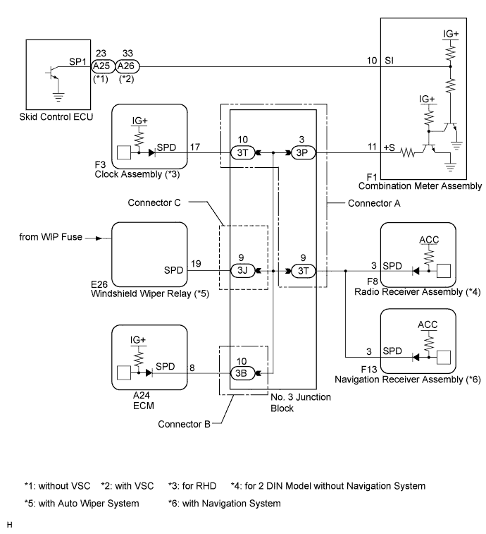
WIRING DIAGRAM

E136588E01

INSPECTION PROCEDURE


1. CHECK COMBINATION METER SYSTEM
  1. The circuits that send vehicle speed signals to this system are inspected in the meter system (Click here).

  1. During inspection for the meter section, if there is an instruction that indicates to go back inspections for each system, proceed to the next step.

NEXT


2. CHECK HARNESS AND CONNECTOR (NAVIGATION RECEIVER ASSEMBLY - COMBINATION METER)

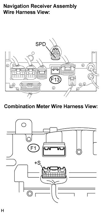
  1. E137736E01
    Disconnect the navigation receiver assembly connector F13 and combination meter connector F1.

  1. Measure the resistance according to the value(s) in the table below.

    Standard resistance:
    Tester Connection
    Condition
    Specified Condition
    F13-3 (SPD) - F1-11 (+S)
    Always
    Below 1 Ω


NG
Go to step 3
OK

PROCEED TO NEXT CIRCUIT INSPECTION SHOWN IN PROBLEM SYMPTOMS TABLE

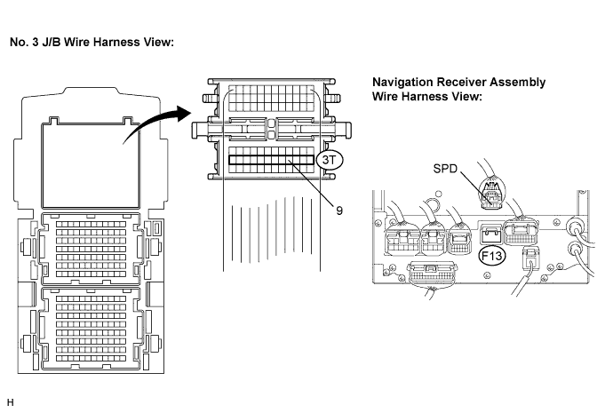
3. CHECK HARNESS AND CONNECTOR (NAVIGATION RECEIVER ASSEMBLY - NO. 3 J/B)

  1. Disconnect the No. 3 J/B connector.E141015E01

  1. Measure the resistance according to the value(s) in the table below.

    Standard resistance:
    Tester Connection
    Condition
    Specified Condition
    3T-9 - F13-3 (SPD)
    Always
    Below 1 Ω


NG
REPAIR OR REPLACE HARNESS OR CONNECTOR
OK

REPLACE NO. 3 JUNCTION BLOCK


← Black Screen (from Jun 2009)Vehicle Speed Signal Circuit between Navigation Receiver Assembly and Combination Meter (Oct 2006 – May 2009) →