TL14 Back-up Battery Voltage Too Low
Diagnostic trouble codes · Vehicles built from Oct 2006
DESCRIPTION
The back-up battery is housed in the battery compartment of the mayday ECU. The back-up battery will provide power to the mayday ECU for at least 30 minutes in the event of the vehicle battery being discharged or disconnected.The mayday ECU has a back-up battery charging circuit that maintains the back-up battery state of charge. This circuit also includes an over-current protection device.
DTC TL14 is set if the back-up battery voltage is less than 6.6 V for more than three minutes.
INSPECTION PROCEDURE
| 1. MONITOR BACK-UP BATTERY VOLTAGE |

Connect the Toyota Link Diagnostic Tool.
Turn the engine switch on (IG).
From the System Menu select: Diagnosis / Data List.
Scroll to the Back-up Battery Voltage Monitor.
Is the voltage as specified?
- Specification:
- Greater than 6.6 V
|
|
||||

| YES | |
 |
| 2. CHECK DTCs |
From the System Menu select: Diagnosis / DTC List / Current DTC / Clear Current DTCs.
Select: Back / History DTC / Clear History DTCs.
Start the engine and increase the engine speed to 1000 rpm for at least 5 minutes.
From the System Menu select: Diagnosis / DTC List / Current DTC.
Is DTC TL14 reset?
|
|
||||

| YES | |
|
| 3. CHECK VEHICLE BATTERY (VOLTAGE) |
Using a digital multi-meter, measure the vehicle battery voltage.
- OK:
- 10 - 14 V
|
|
||||
| OK | |
|
| 4. CHECK MAYDAY ECU UNIT (VOLTAGE AND GROUND) |
Disconnect the mayday ECU unit connector N46 and check for voltage.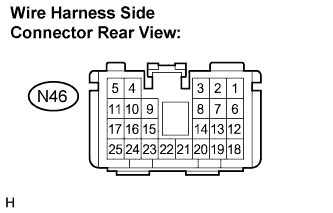

- Standard:
Terminals No.
Specification
N46-3 - N46-4
10 - 14 V
|
|
||||
| OK | |
|
| 5. CHECK MAYDAY ECU WIRE HARNESS |
Disconnect the mayday ECU connector B and check for continuity.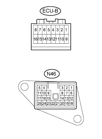
- Standard:
Symbol (Terminals No.)
Specification
- (N46-3) - B+ (B-16)
Below 1 Ω
- (N46-4) - GND (B-8)
|
|
||||
| OK | |
|
| 6. CHECK BACK-UP BATTERY TERMINAL RETENTION |
Are the back-up battery terminals tight?
|
|
||||
| YES | |
|
| 7. CHECK THE BACK-UP BATTERY VOLTAGE |
Back-probe the back-up battery connector ECU-E a the mayday ECU.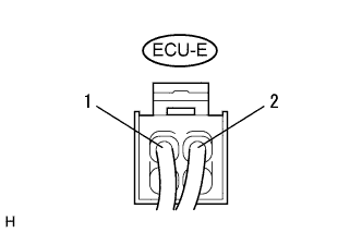
Connect a digital multimeter between the terminals and 2 and check for voltage.
- OK:
- Greater than 6.6 V
|
|
||||
| OK | ||
 |
||
| ||
| 8. INSPECT BACK-UP BATTERY CHARGING CYCLE |
Turn the engine switch on (IG).
From the System Menu select: Diagnosis / Data List.
Read the 'Back-up Battery Charger' and 'Back-up Battery Monitor' status from the data list.
- Result:
Back-up battery monitor
Proceed to
Below 6.6 V, Back-up battery charger: ON
A
Below 6.6 V, Back-up battery charger: OFF
B
|
|
||||
| B | |
|
| 9. RESET MAYDAY ECU |
Turn the engine switch on (IG).
From the System Menu select: Function Set / Rest Module.
Select: Back / Diagnosis / Data List.
Read the 'Back-up Battery Charger' and 'Back-up Battery Monitor' status from the data list.
- Result:
Back-up battery monitor
Proceed to
Below 6.6 V, Back-up battery charger: OFF
C
Below 6.6 V, Back-up battery charger: ON
D
|
|
||||
| D | |
|
| 10. MONITOR CHARGE STATUS |
Leave the back-up battery to charge for 1 hour.
Read the 'Back-up Battery Monitor' status from the data list.
Is the voltage as specified?
- Specification:
- Greater than 6.6 V
|
|
||||
| YES | ||
|
||
| ||